
Motor driver system and method for protecting motor driver

Inactive Publication Date: 2008-12-04
LG ELECTRONICS INC
View PDF3 Cites 4 Cited by
  • Summary
  • Abstract
  • Description
  • Claims
  • Application Information

AI Technical Summary

Benefits of technology

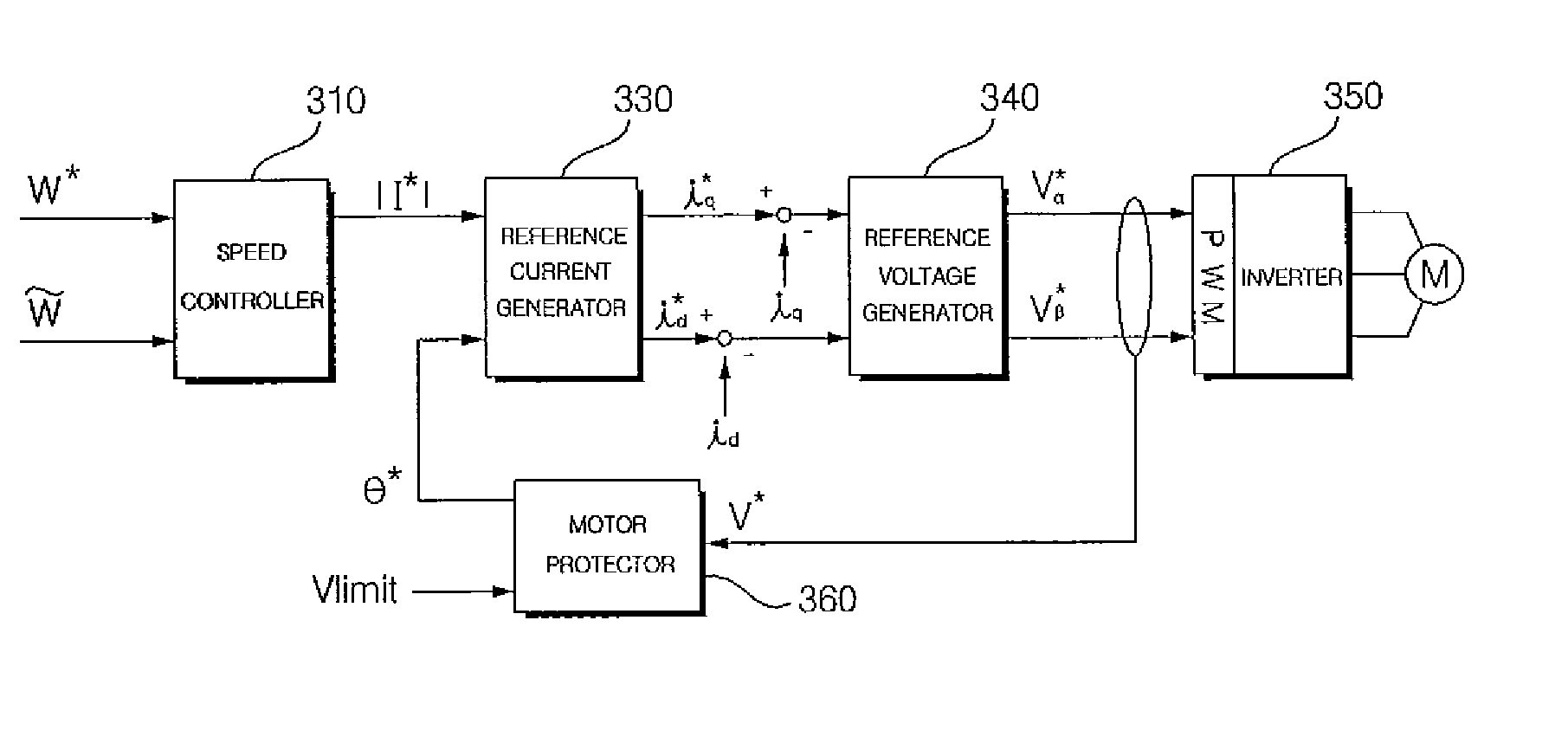
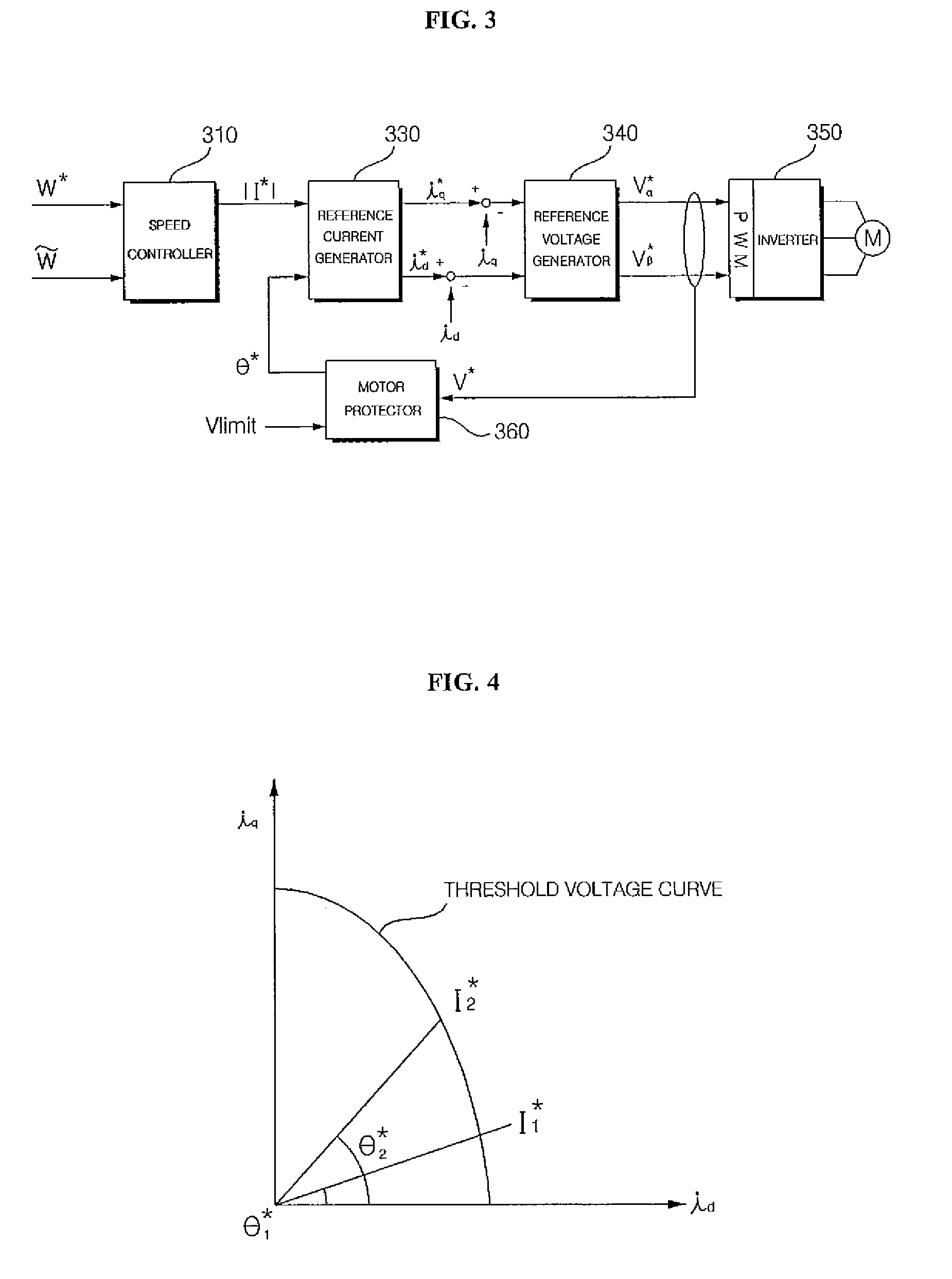
[0016]It is an object of the present invention to make a reference voltage to follow a preset voltage by changing a reference current angle, thereby controlling the reference voltage not to exceed a DC voltage source limitation.
[0017]Although the reference current value may be changed due to the va

Problems solved by technology

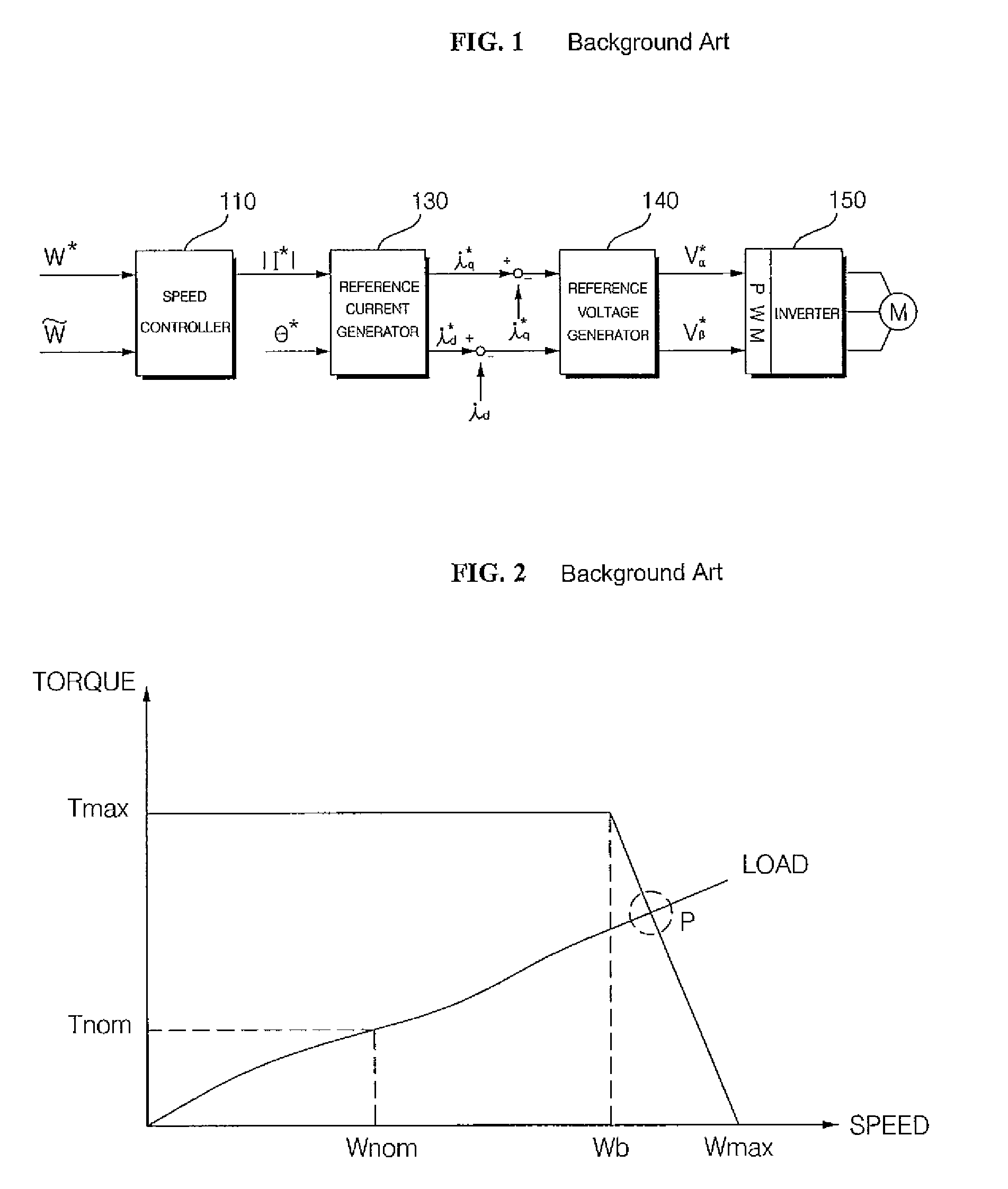
In this case, it becomes difficult to control the motor.
In this case, it is difficult to stably control the speed of the motor.
In the worst case, the motor or the driver may be damaged.
Therefore, when the load is located at an overload point P where a speed is higher than the base speed ωb, it is difficult to control the motor stably by applying a reference voltage value higher than a threshold value to the motor.

Method used


Image

  • Motor driver system and method for protecting motor driver
  • Motor driver system and method for protecting motor driver
  • Motor driver system and method for protecting motor driver

Examples


Embodiment Construction

[0031]The embodiments of the present invention will be described in a more detailed manner with reference to the drawings.

[0032]Hereinafter, a motor driver system and a method for protecting a motor according to embodiments of the present invention will be described with reference to the accompanying drawings.

[0033]FIG. 3 is a block diagram illustrating a motor driver system including a motor protector for controlling a reference voltage value not to exceed a voltage threshold value according to an embodiment of the present invention.

[0034]Referring to FIG. 3, a speed controller 310 outputs a reference current value |I*| that makes a difference between a reference speed ω* and a presumed speed {tilde over (ω)} be zero (0). For example, the presumed speed {tilde over (ω)} may be obtained using a sensor-less algorithm. If the presumed speed {tilde over (ω)} is obtained through a sensor such as Hall IC, the speed controller 310 outputs a reference current value that can make the differ...


PUM


Abstract

A motor driver system includes an inverter configured to apply a three-phase voltage to a motor; an inverter driver configured to generate a reference voltage to the inverter to control a motor speed to follow a reference speed; and a motor protector configured to control the inverter driver so that a value of the reference voltage is equal to or lower than a predetermined voltage value.

Description

[0001]This Nonprovisional application claims priority under 35 U.S.C. §119(a) on Patent Application No. 10-2007-0052270 filed in Korea on May 29, 2007, the entire contents of which are hereby incorporated by reference.BACKGROUND OF THE INVENTION[0002]1. Field of the Invention[0003]The present invention relates to a motor driver system and a motor protecting method for stably controlling a motor even when the motor is driven at a high speed or is overloaded.[0004]2. Description of the Background Art[0005]A motor is controlled to rotate a rotor at a desired rotation speed. That is, when the speed of rotating the rotor is observed or presumed, the motor is controlled to have the presumed speed or the measured speed to follow a reference speed. An inverter driver generates a three-phase voltage for driving the motor according to a reference voltage that varies according to the reference speed. In order to generate the reference voltage, it is common to generate a reference current.[0006...

Claims


Application Information

Patent Timeline
IPC IPC(8): H02P27/06H02P29/02
CPCH02P21/0085H02P21/0089H02P29/028H02P23/0036H02P21/06H02P23/0004H02P29/032H02H7/085H02P25/08H02P27/06
Inventor LEE, KYUNG HOONWON, JUNE HEELEE, GIL SUAHN, JUN HOOH, JAE YOON
Owner LG ELECTRONICS INC
Learn More