Communication control apparatus and communication control method
- Summary
- Abstract
- Description
- Claims
- Application Information
AI Technical Summary
Benefits of technology
Problems solved by technology
Method used
Image
Examples
first embodiment
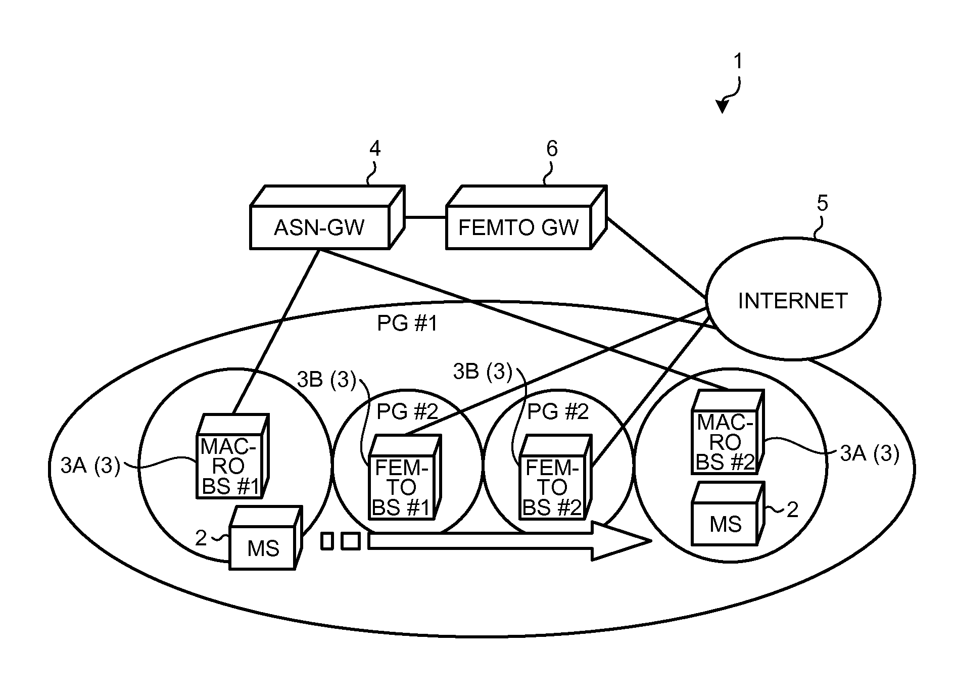
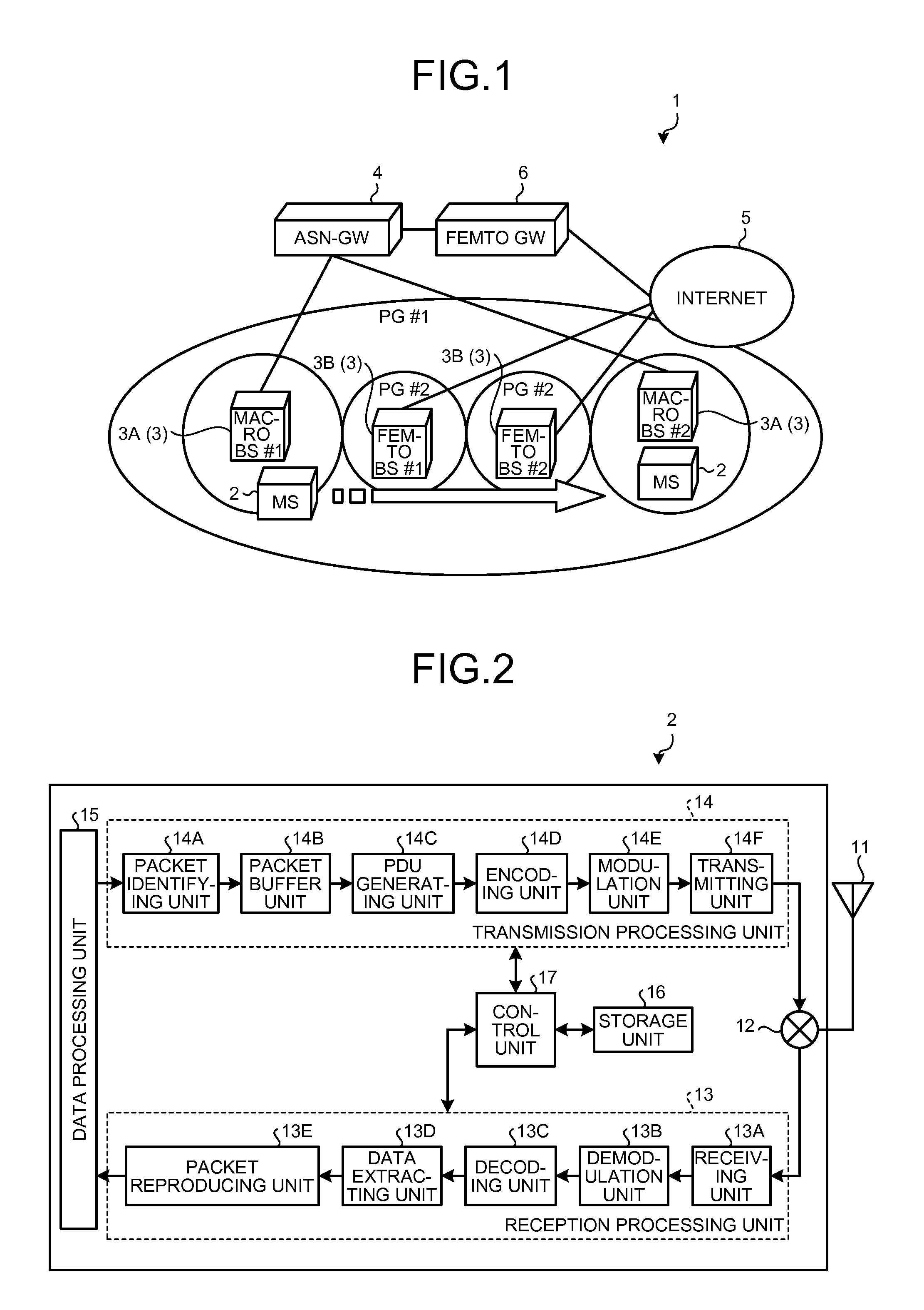
[0099]FIG. 1 is an explanation diagram illustrating the schematic configuration of a wireless communication system 1 according to the first embodiment.
[0100]The wireless communication system 1 illustrated in FIG. 1 includes a plurality of BSs 3 that wirelessly accommodates a plurality of MSs 2, an ASN-GW 4 that accommodates macro BSs 3A of the plurality of BSs 3, and a femto GW 6 that accommodates femto BSs 3B of the plurality of BSs 3 by way of Internet 5. The ASN-GW 4 accommodates the femto BSs 3B by way of the femto GW 6 and the Internet 5.
[0101]The wireless communication system 1 sets PG #1 in the plurality of macro BSs 3A that is geographically adjacent and sets PG #2 different from the PG of the macro BSs 3A in the plurality of femto BSs 3B that is not geographically adjacent. In other words, PG for the femto BSs 3B is the same common PG.
[0102]Moreover, the femto GW 6 uses an IP security between it and each the femto BS 3B to set a point to point encryption tunnel and prevents...
second embodiment
[0184]Now, a wireless communication system that deals with the above situation will be explained as the second embodiment. FIG. 9 is an explanation diagram illustrating the schematic configuration of a wireless communication system 1A according to the second embodiment. The same configuration as that of the wireless communication system 1 of the first embodiment illustrated in FIG. 1 has the same reference number, and the explanations of the same configuration and operation are omitted.
[0185]In the wireless communication system 1A illustrated in FIG. 9, the PG #1 is set for the plurality of geographically adjacent macro BSs 3A, and the PG #2 common to the femto BSs 3B and the same PG as that of the neighboring macro BSs 3A are set for the plurality of femto BSs 3B.
[0186]In other words, for example, two PGs of the PG #2 common to the femto BSs 3B and the PG #1 of the neighboring macro BSs 3A “#1” and “#2” are set for the femto BS 3B “#1”.
[0187]Next, it will be explained about operati...
third embodiment
[0234]Now, a wireless communication system that deals with the above situation will be explained as the third embodiment. The same configuration as that of the wireless communication system 1A of the second embodiment illustrated in FIG. 9 has the same reference number, and the explanations of the same configuration and operation are omitted.
[0235]In the wireless communication system according to the third embodiment, when the macro BSs 3A and the femto BS 3B are in the same PG, paging information of the MS 2 is continuously transmitted through all the macro BSs 3A in the same PG for a predetermined time even if the MS 2 is in the same PG and then the paging information of the MS 2 is transmitted through the femto BS 3B in the same PG when a response to paging information is not detected in a predetermined time.
[0236]FIG. 12 is an operating sequence diagram illustrating processing operations of a wireless communication system 1B associated with a paging process according to the thir...
PUM
 Abstract
Description
Claims
Application Information
 - R&D
- Intellectual Property
- Life Sciences
- Materials
- Tech Scout
- Unparalleled Data Quality
- Higher Quality Content
- 60% Fewer Hallucinations
Browse by: Latest US Patents, China's latest patents, Technical Efficacy Thesaurus, Application Domain, Technology Topic, Popular Technical Reports.
© 2025 PatSnap. All rights reserved.Legal|Privacy policy|Modern Slavery Act Transparency Statement|Sitemap|About US| Contact US: help@patsnap.com


