Motor control apparatus for correcting interpolation error of position detector

Active Publication Date: 2015-08-06
FANUC LTD
View PDF9 Cites 1 Cited by
  • Summary
  • Abstract
  • Description
  • Claims
  • Application Information

AI Technical Summary

Benefits of technology

The present invention aims to provide a motor control system that can effectively control a motor even if there is a position detection error in the position detector.

Problems solved by technology

Interpolation, however, has an error, and the error is generated every time a rotor of a motor rotates one time.
A position detection error caused by an interpolation error thus cyclically appears in an output of a position detector.
By the position detection error, a speed command or a torque command which is generated by a motor control apparatus cyclically oscillates, and as the result, noise is generated from a motor which is driven and controlled by the motor control apparatus, which is problematic.
A position detector provided in a motor control apparatus has a cyclic position detection error caused by an interpolation error.
Among the above commands, a torque command which is generated by a motor control apparatus using a position detection value including a position detection error cyclically oscillates, and therefore a noise is generated from a motor when rotational drive of the motor is controlled by using such a torque command.
However, an existing position detector not having such a correction function therein needs to be provided with the correction function therein in such a manner that the correction function is physically added thereto, and therefore, in some cases, it is difficult to add the correction function thereto or the cost increases depending on the structure of the position detector, which are problematic.

Method used


Image

  • Motor control apparatus for correcting interpolation error of position detector
  • Motor control apparatus for correcting interpolation error of position detector
  • Motor control apparatus for correcting interpolation error of position detector

Examples


first embodiment

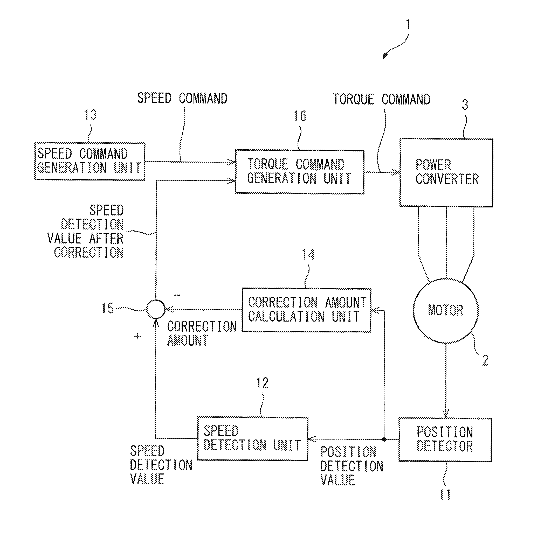
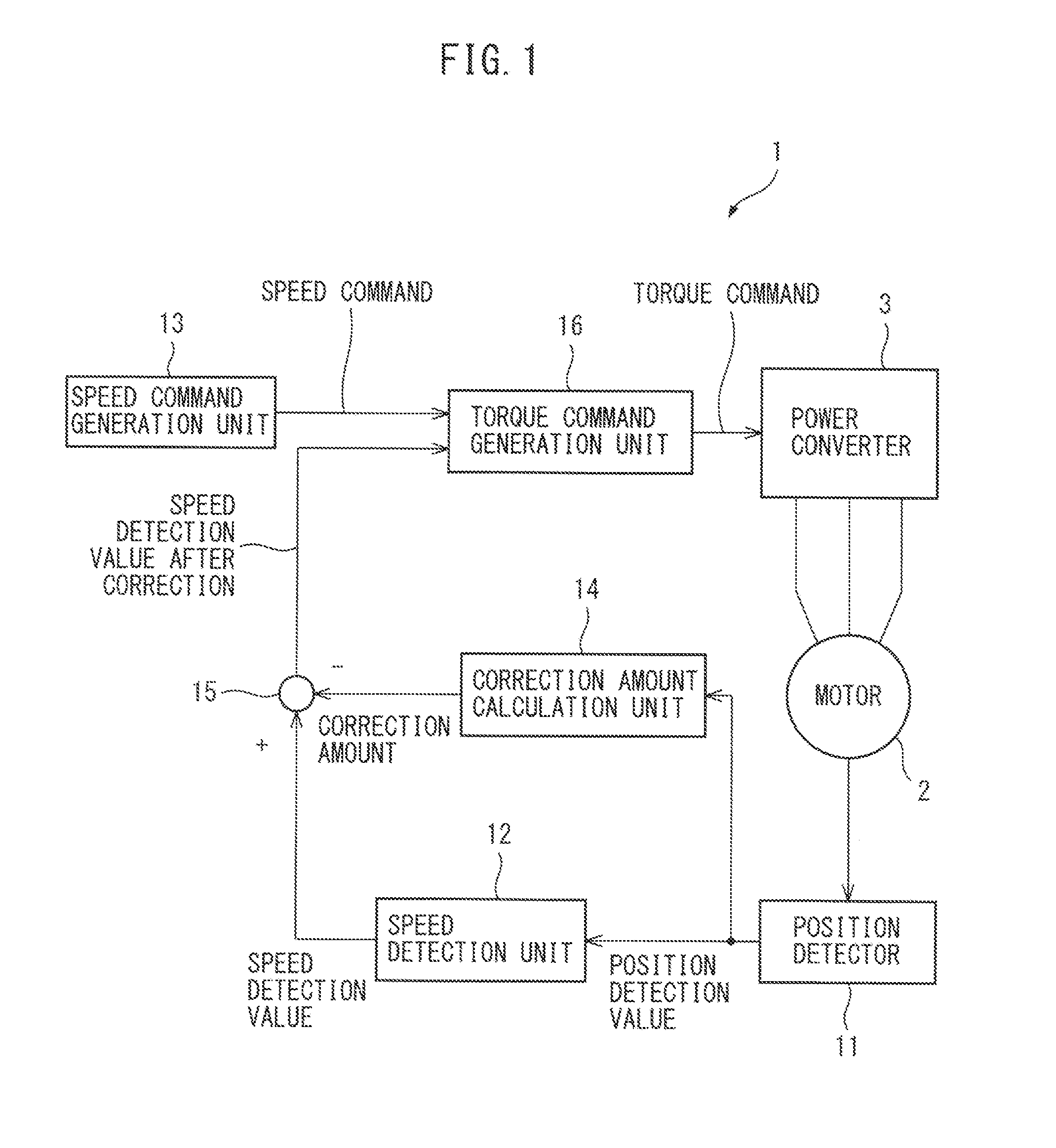
[0023]FIG. 1 is a block diagram illustrating a motor control apparatus of the Here, an example in which a motor 2 is rotationally driven by a motor control apparatus 1 will be explained. A driving power of the motor 2 is generated by a power converter 3. The power converter 3 is constituted by a conversion circuit (not illustrated) including a switching element therein such as a PWM inverter. The power converter 3 converts a direct-current power to a three-phase alternating current power having a desired voltage and a desired frequency for rotationally driving a motor 2 by allowing a switching element provided therein to perform switching operation based on a torque command generated by the motor control apparatus 1. The motor 2 operates based on a supplied voltage variable and frequency variable three-phase alternating current power.

[0024]The motor control apparatus 1 of the first Embodiment includes: a position detector 11 for detecting the position of a rotor of the motor 2; a s...

second embodiment

[0039]The motor control apparatus 1 of the second Embodiment includes: a position detector 11 for detecting the position of a rotor of a motor 2; a speed detection unit 12 for calculating a speed detection value based on a position detection value detected by the position detector 11; a speed command generation unit 13 for generating a speed command which commands a rotation speed of the rotor of the motor 2; a torque command generation unit 21 for generating a torque command which commands a rotational torque of the motor based on the speed command and the speed detection value; a correction amount calculation unit 22 for calculating a correction amount based on the position detection value detected by the position detector 11; and a correction processing unit 23 for correcting a torque command by using the correction amount. Specific examples of the position detector 11 include a rotary encoder or a linear scale.

[0040]FIG. 5 is a drawing explaining operations of a correction amoun...


PUM


Abstract

A motor control apparatus comprises a position detector for detecting the position of a rotor of a motor, a speed detection unit for calculating a speed detection value based on a position detection value detected by the position detector, a speed command generation unit for generating a speed command which commands a rotation speed of the rotor of the motor, a correction amount calculation unit for calculating a correction amount based on the position detection value detected by the position detector, a correction processing unit for correcting the speed detection value by using the correction amount, and a torque command generation unit for generating a torque command which commands a rotational torque of the motor based on the speed command and the speed detection value corrected by the correction processing unit.

Description

BACKGROUND OF THE INVENTION[0001]1. Field of the Invention[0002]The present invention relates to a motor control apparatus comprising a position detector for detecting the position of a rotor of a motor.[0003]2. Description of the Related Art[0004]In order to detect the position of a rotor of a motor, a position detector such as a rotary encoder or a linear scale is provided in a motor control apparatus for controlling rotational drive of the motor. A position detection value detected and fed back by the position detector is utilized for generating a speed command or a torque command for a motor.[0005]A position detector realizes a high resolving power by further electrically interpolating (dividing) a physical scale. Interpolation, however, has an error, and the error is generated every time a rotor of a motor rotates one time. A position detection error caused by an interpolation error thus cyclically appears in an output of a position detector. By the position detection error, a ...

Claims


Application Information

Patent Timeline
IPC IPC(8): G05B11/01
CPCG05B11/011
Inventor TSUNEKI, RYOUTAROU
Owner FANUC LTD
Why Eureka
Try Eureka