Control device and control method for power supply device

Active Publication Date: 2017-01-05
TDK CORPARATION
View PDF6 Cites 3 Cited by
  • Summary
  • Abstract
  • Description
  • Claims
  • Application Information

AI Technical Summary

Benefits of technology

The technical effect of this patent is to provide a control device and method for a power supply device that can perform stable constant voltage and constant current control with high responsiveness even using a simple configuration. This makes it easier to control the power supply and ensures a stable output.

Problems solved by technology

The lithium ion battery is characteristically prone to degradation if kept in a full charge state, and thus not suited for trickle charging.
The lithium ion battery can possibly cause fire if overcharged.
In such a case, if the major loop changes the target value while the control of the minor loop is in operation, the control of the minor loop can become unstable.
If the CC control is the major loop, there can occur a problem due to the low response speed.
The result has been high costs and low versatility of the CV control minor loop / CC control major loop cascade system.
The uses of the CC control minor loop / CV control major loop cascade system have thus been limited to a bidirectional power supply device, a power factor improvement step-up converter, and the like of which high response speed is not needed.
However, according to the parallel control system, the CC control unit 111 and the CV control unit 112 constantly generate the CC control operation amount Ui and the CV control operation amount Uv regardless of which is selected as the operation amount U. There has thus been a problem of unstable control due to a change in the operation amount U when control is switched from CC control to CV control or from CV control to CC control.
There has thus been a problem that it takes long to converge to a stable state.
There has thus been a problem of complicated control.
There has thus been a problem of increased installation space as well as an increase in the cost of the control device 110.

Method used


Image

  • Control device and control method for power supply device
  • Control device and control method for power supply device
  • Control device and control method for power supply device

Examples


Embodiment Construction

[0041]An embodiment of the present invention will be described below with reference to the accompanying drawings.

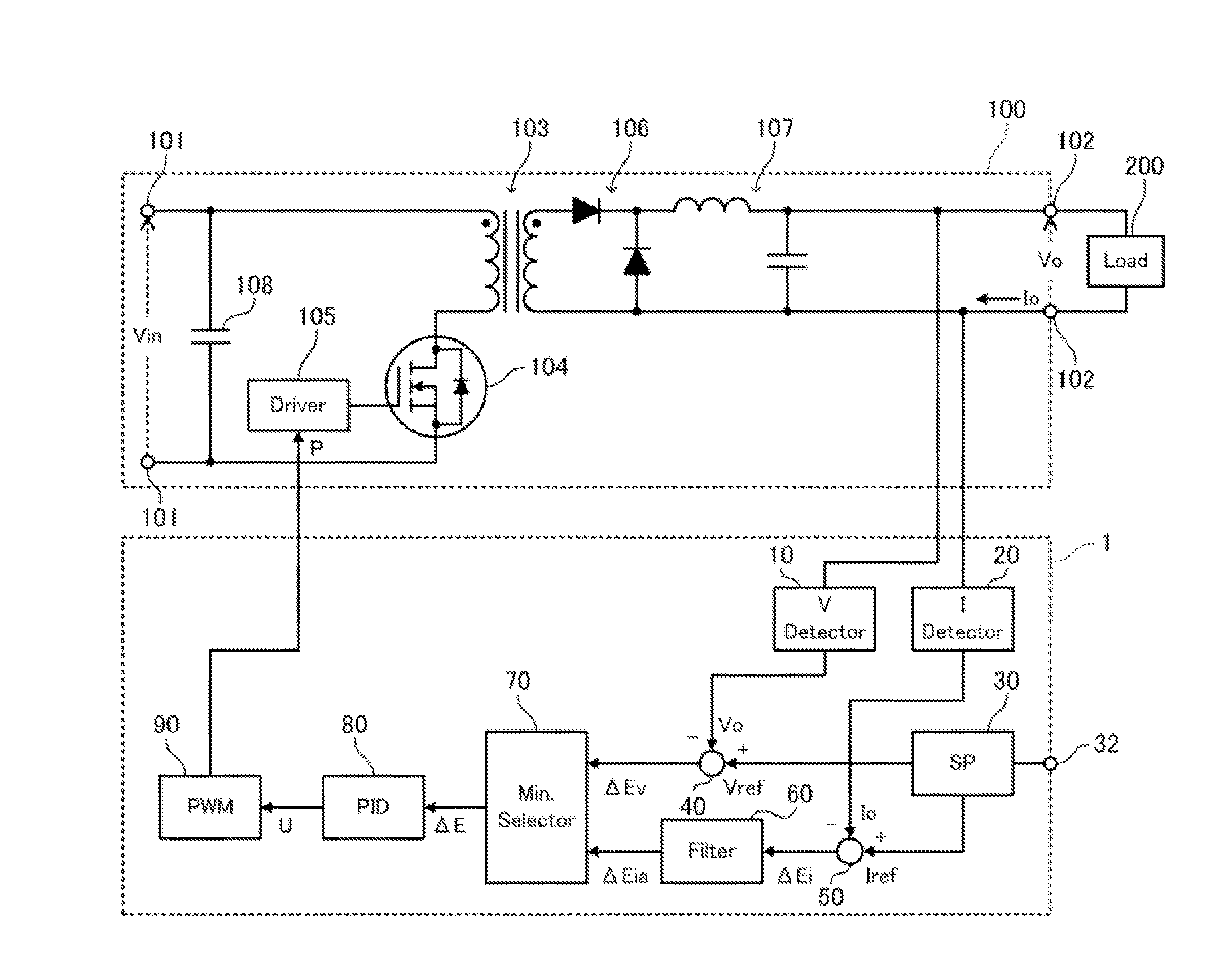
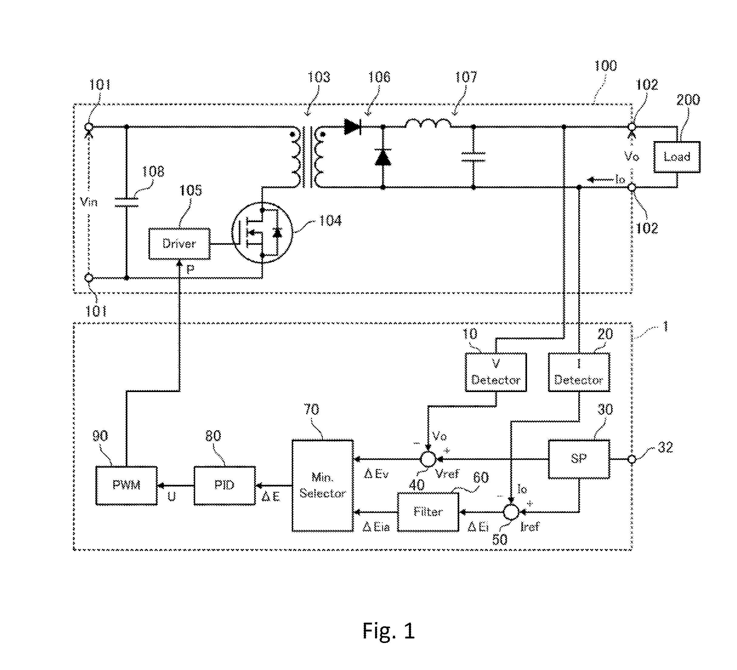
[0042]FIG. 1 a block diagram showing a configuration of a control device 1 for a power supply device (hereinafter, referred to simply as a control device 1) according to the present embodiment. The control device 1 performs output CVCC control (constant voltage constant current control) on a power supply device 100 such as a DC / DC converter.

[0043]Like the foregoing conventional examples, the power supply device 100 according to the present embodiment is a single-transistor forward converter including a known configuration. Specifically, the power supply device 100 includes a pair of input terminals 101, a pair of output terminals 102, a transformer 103, a switch 104, a driver 105, a rectifier circuit 106, a smoothing circuit 107, and an input capacitor 108. A direct-current voltage having an input voltage value of Vin is applied to the pair of input terminals 101. A load ...


PUM


Abstract

A control device and method are provided for a power supply device which can perform stable constant voltage constant current control with high responsiveness with a simple configuration. The control device includes: a voltage difference value generation unit which subtracts an output voltage value from a voltage target value to generate a voltage difference value; a current difference value generation unit which subtracts an output current value from a current target value to generate a current difference value; a difference value selection unit which compares the voltage difference value or a value based on the voltage difference value with the current difference value or a value based on the current difference value, and selects the smaller one as a control difference value; and an operation amount generation unit which generates an operation amount for controlling the power supply device based on the control difference value.

Description

BACKGROUND OF THE INVENTION[0001]1. Field of the Invention[0002]The present invention relates to a control device and a control method for a power supply device such as a DC / DC converter and an AC / DC converter, and more particularly to a control device and a control method for performing constant voltage constant current control.[0003]2. Description of the Related Art[0004]In the field of power supply such as a commercial power source, renewable energies like solar power generation and wind power generation are becoming widespread. Under the circumstances, a smart grid, a next-generation power infrastructure equipped with means for compensating mismatches between demand and supply through the use of secondary batteries, has been being built recently. In the field of automobiles, plug-in hybrid electric vehicles (PHEVs), electric vehicles (EVs), and the like of which secondary batteries can be charged with a commercial power source etc., as well as conventional hybrid vehicles (HVs) ...

Claims


Application Information

Patent Timeline
IPC IPC(8): H02M3/335H02M1/08
CPCH02M3/335H02M7/217H02M3/33546H02M1/0009
Inventor TAKEGAMI, EIJI
Owner TDK CORPARATION
Why Eureka
Try Eureka