Solar charger

a solar charger and charger body technology, applied in the field of solar chargers, can solve the problems of inability to efficiently charge rechargeable batteries, inability to stably hold a set angle of inclination, and narrow groove pitch, so as to avoid wasted energy

Inactive Publication Date: 2008-12-04
GK BRIDGE 1
View PDF6 Cites 14 Cited by
  • Summary
  • Abstract
  • Description
  • Claims
  • Application Information

AI Technical Summary

Benefits of technology

[0021]Further, since the case of the solar charger above contains an internal battery, which is charged by the solar cell, and can charge the rechargeable battery, wasted energy can be avoided by storing solar cell power in the internal battery when no rechargeable battery is loaded or when a rechargeable battery is fully charged. In addition, when charging the rechargeable battery loaded in the solar charger, both the solar cell and the internal battery can charge the rechargeable battery to attain full charge in a short period. Finally, even when no output is obtained from the solar cell, the rechargeable battery can be charged via the internal battery.

Problems solved by technology

However, because a solar charger with this configuration has an overall cylindrical shape, it has the drawback that it cannot stably hold a set angle of inclination when set with a groove or flat resting on the horizontal surface.
As a result, it has the drawback that if, for example, the supporting surface vibrates or there is a slight jolt, the angle of inclination changes and rechargeable batteries cannot be efficiently charged.
In particular, if many grooves or flats are provided to allow placement in accordance with the sun's angle of elevation, which changes over the four seasons, the pitch of the grooves becomes narrower and stable placement becomes even more difficult.

Method used


Image

  • Solar charger
  • Solar charger
  • Solar charger

Examples


Embodiment Construction

)

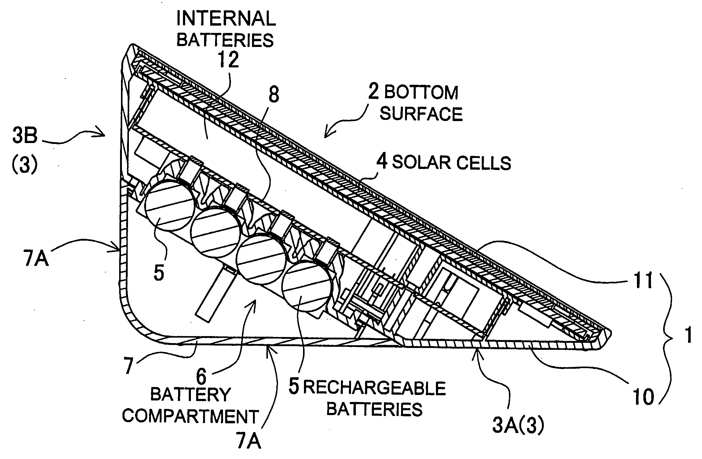
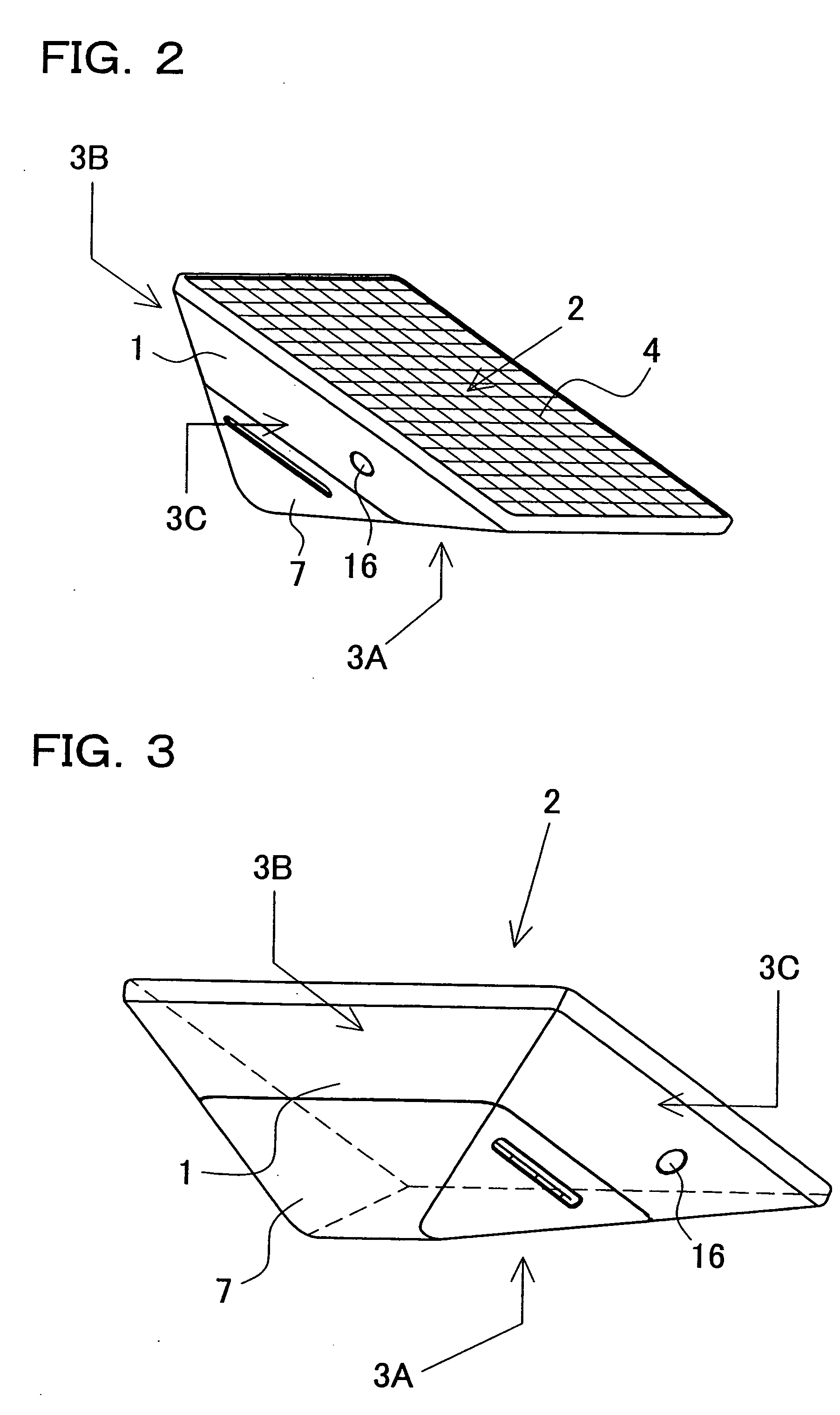
[0043]The solar charger (or solar re-charger) shown in FIGS. 2-10 is provided with a case 1 having a battery compartment 6 to hold rechargeable batteries 5 in a removable fashion, and solar cells 4 fixed to the case 1 to supply charging power to the rechargeable batteries 5.

[0044]The case 1 is formed in a shape that has a bottom surface 2 and at least two tapered surfaces 3 having different slope angles (α) with respect to the bottom surface 2. The case 1 shown in FIGS. 2-7 has an overall pyramid-shape. The case 1 shown in FIGS. 2-7 is formed in a pyramid-shape having a polygonal bottom surface 2 with a plurality of tapered surfaces 3 at its perimeter. However, in the present application, a pyramid-shape is not necessarily limited to a shape having a vertex region that forms a vertex point opposite the bottom surface. For example, the case 1 shown in FIGS. 2-7 is not a perfect pyramid with four sides and a base, but rather the vertex region has a ridge that forms a rooftop-type pse...


PUM

PropertyMeasurementUnit
slope angleaaaaaaaaaa

Abstract

The solar charger is provided with a case 1 that can hold a rechargeable battery 5 in a removable fashion, and a solar cell 4 to supply charging power to the rechargeable battery 5 loaded in the case 1. The case 1 is formed in a shape having a bottom surface 2 and at least two tapered surfaces 3 with different slope angles α with respect to the bottom surface 2, and the solar cell is disposed on the bottom surface 2. The angle of inclination θ of the solar cell 4 provided on the bottom surface 2 of the solar charger is changed by disposing a tapered surface 3 having a different slope angle α on a flat surface.

Description

BACKGROUND OF THE INVENTION[0001]1. Field of the Invention[0002]This invention relates to a solar charger that charges a rechargeable battery via a solar cell, and in particular relates to a solar charger that can efficiently charge a rechargeable battery over the four seasons of the year.[0003]2. Description of the Related Art[0004]Solar cells produce electricity most efficiently when oriented perpendicular to the sun's rays. This is because solar energy is most efficiently transferred to solar cells irradiated in this orientation. The sun's rays irradiate solar cells with energy of approximately 1 KW per square meter. Consequently, solar cells with an energy conversion efficiency of 10% generate 100 W of electricity per square meter. However, if the solar cells are inclined at an angle of 45° with respect to the sun's rays, solar energy supplied to the solar cells drops by 30%. If the solar cells are further inclined to an angle of 60°, solar energy supplied to the solar cells dro...

Claims


Application Information

Patent Timeline
Patent Type & Authority Applications(United States)
IPC IPC(8): H01M10/44H02J7/00
CPCF24J2002/0416H01M6/42H02S40/38H02J7/355H01M10/465F24S2020/186H02J7/35Y02E10/56Y02E60/10Y02E70/30
Inventor TOYA, SHOICHIFUKUKAWA, KOICHI
Owner GK BRIDGE 1
Why Eureka
Try Eureka