RF detector with crest factor measurement

a detector and crest factor technology, applied in the field of rf detectors, can solve the problems of reducing degrading the accuracy of the measurement, especially of the crest factor measurement, and adding complexity and cost to the system, so as to increase the input dynamic range and accurate divider

Active Publication Date: 2008-12-04
HITTITE MICROWAVE LLC
View PDF99 Cites 41 Cited by
  • Summary
  • Abstract
  • Description
  • Claims
  • Application Information

AI Technical Summary

Benefits of technology

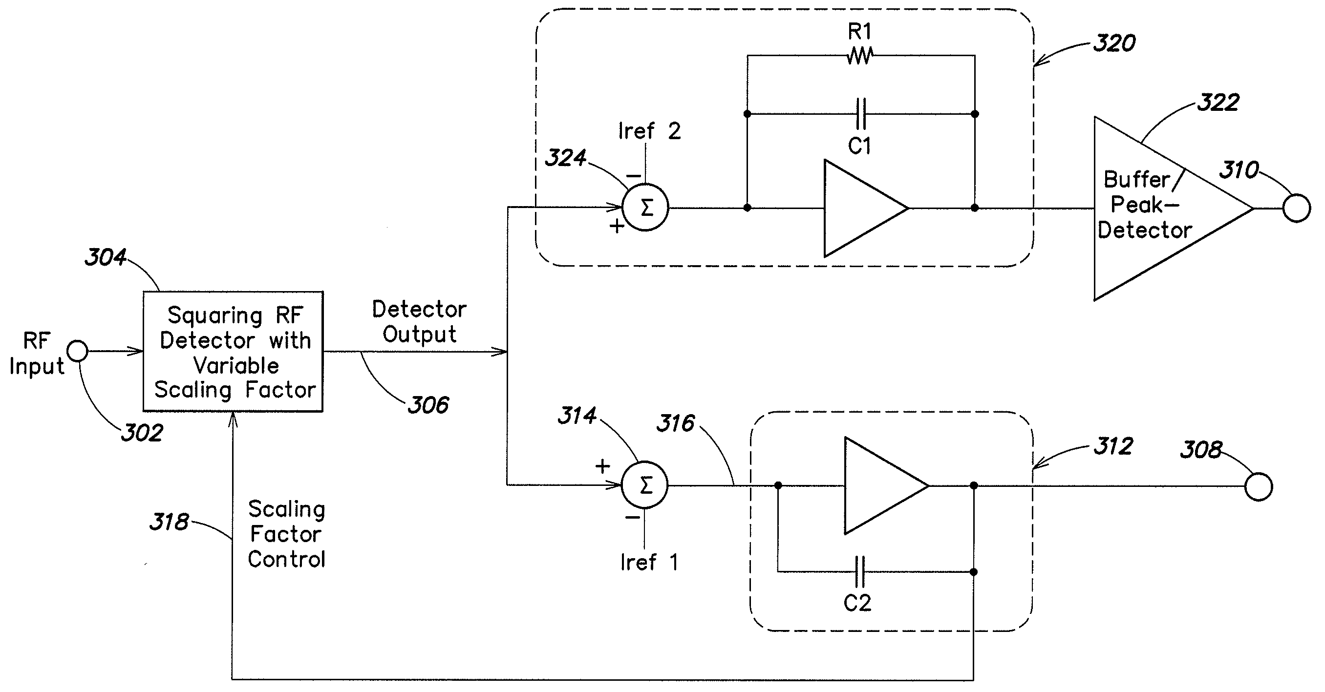
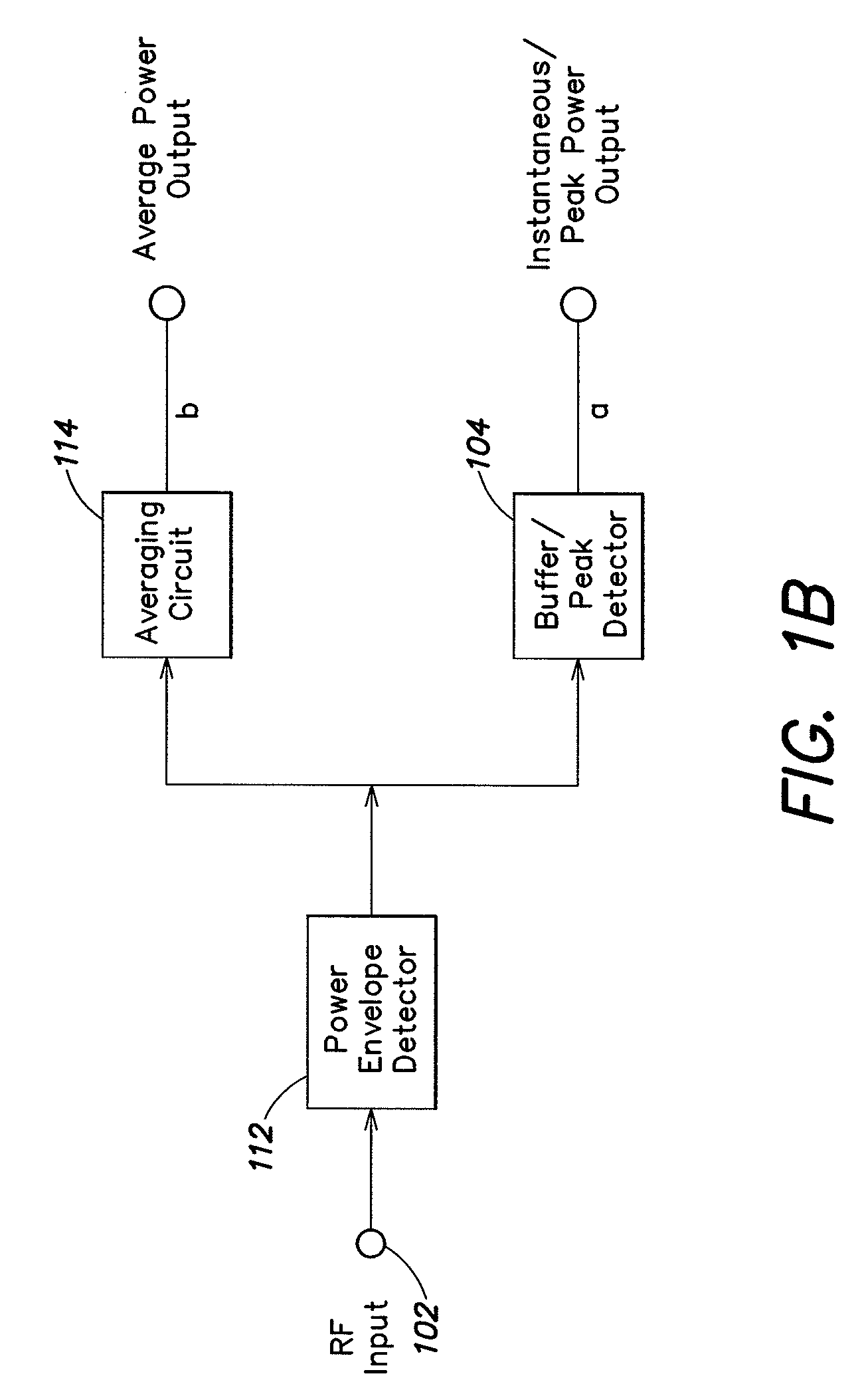
[0013]Aspects and embodiments of the present invention are directed to a wide-dynamic range RF detector that accepts a modulated or unmodulated RF input signal and provides an output which varies as a quasi-linear function of the logarithm of the RMS value of the RF input signal voltage. That is, the RF detector provides an output that varies linearly (or nearly so) with the RMS voltage measured in dB of the RF input signal. The RF detector is also capable of providing a second output representative of the instantaneous or peak power level, of the RF input signal, normalized to the average power of the signal. Embodiments of the RF detector use a single detector array for both average (e.g., RMS) power detection and instantaneous / peak power detection, thereby eliminating some of the part-to-part, process and / or temperature variability issues which may exist with conventional systems, as discussed above. In addition, embodiments of the RF detector implement a feedback control loop to increase the input dynamic range and normalize the measured instantaneous / peak power to the average power, thereby removing the need for an accurate divider. Thus, as discussed further below, the RF detector circuit according to aspects and embodiments of the invention may be used to provide accurate indications of the average power level, normalized instantaneous power level, and peak-to-average power ratio (crest factor) of an RF signal over a wide range of input power levels and modulation complexity.

Problems solved by technology

These complex modulated signals have a time varying crest factor, which is defined as the peak to average power ratio of the signal, resulting in intolerable errors if conventional power detectors using diode detection or successive amplification are used to measure signal power.
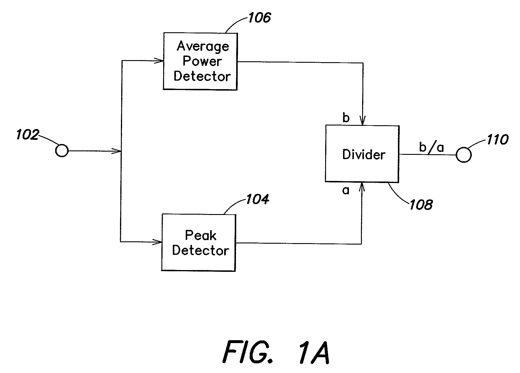
A disadvantage of RF detectors using the parallel processing technique is that an RF coupler (not shown) is required at the input 102 to drive both the average power detection channel and the envelope power or peak power detection channel.
In addition, because different detectors (104 and 106) are used in the two different detection channels, there may exist part-to-part, process, and temperature variations between the two channels, which can degrade the accuracy of the measurements, particularly of the crest factor measurement.
Matching circuitry may be required to compensate for such differences between the two channels, adding complexity and cost to the system.
Another disadvantage is that the divider 108 may be required to handle nonlinear calculations depending on the output characteristics of the average power detection channel and the envelope power or peak power detection channel.
In addition, because any inaccuracy in the divider would compromise the crest factor measurement, an accurate, possibly complex and expensive, divider may be required.
However, in a system such as that illustrated in FIG. 1A, where both peak / envelope and average power are measured, the normalized instantaneous power output or peak power output would be limited by the lesser performance (dynamic range) of the envelope power or peak power detecting scheme.
In addition, single-detector envelope power or peak power detecting scheme are generally also highly dependent on the input RF frequency, which may not be desirable in many applications.

Method used


Image

  • RF detector with crest factor measurement
  • RF detector with crest factor measurement
  • RF detector with crest factor measurement

Examples


Embodiment Construction

[0046]There is a wide range of applications in which providing an accurate measurement or representation of both the true RMS (root-mean-square) power and an indication of the instantaneous or peak power of an RF signal may be advantageous. For example, in communications systems signal power level measurements may be used to provide a received signal strength indication (RSSI) and / or a transmitter signal strength indication (TSSI). These signal power measurements may also be used for RF power amplifier efficiency control, receiver automatic gain control, and / or transmitter power control. As discussed above, some systems involve complex modulated signals (e.g., CDMA, WCDMA or WiMAX wireless communication systems). These systems may benefit from accurate average power information that is independent of the modulation scheme. In some communication systems, instantaneous or peak power level information, in combination with RMS average power level information may be critical to avoid sat...


PUM


Abstract

An RF detector configured to provide two outputs, one being a function of the true RMS power level of an RF input signal, and the other being a function of the instantaneous/peak power of the RF input signal, normalized to the average power level. The RF detector includes a variable gain detection subsystem including a single detector or detector array that provides a representation of the power level of the RF input signal. The detector or detector array is common to both the RMS power detection channel and the instantaneous/peak power detection channel of the RF detector. A method of RF detection includes providing representations of the RF input signal at different gain levels, selecting one or more of the representations, and averaging the selected signals. The gain levels of the selected representations is adjusted to provide information about the average power level of the RF input signal.

Description

CROSS REFERENCE TO RELATED APPLICATIONS[0001]This application claims priority under 35 U.S.C. § 119(e) to U.S. Provisional application No. 60 / 930,120 filed May 14, 2007 and entitled “RF DETECTOR,” which is hereby incorporated by reference in its entirety.BACKGROUND[0002]1. Field of Invention[0003]The present invention relates generally to RF detectors and, more particularly, to RF detectors capable of providing an indication of both the average power and the instantaneous or peak power levels of an RF signal.[0004]2. Discussion of Related Art[0005]There are many applications in which it is desirable to measure the peak and / or average power level of a radio frequency (RF) signal. For example, power measurement and control of the RF signals in both the transmitting and receiving chains of modern wireless communications systems, such as cellular telephone networks, may be essential. To efficiently use the available bandwidth, the transmitted signals in these systems may be modulated us...

Claims


Application Information

Patent Timeline
Patent Type & Authority Applications(United States)
IPC IPC(8): H03G3/00
CPCG01R21/01H03G3/3036
Inventor EKEN, YALCIN ALPERKATZIN, PETER
Owner HITTITE MICROWAVE LLC
Why Eureka
Try Eureka