
Cutting Tooth for Brush Cutting

a technology for cutting teeth and teeth, applied in shaping cutters, manufacturing tools, grain treatment, etc., can solve the problems of affecting the cutting effect of teeth, prone to excessive wear and damage, and the cutting elements of wood shredding, etc., to facilitate the passage of cutting debris

Active Publication Date: 2008-12-04
GYRO TRAC
View PDF22 Cites 15 Cited by
  • Summary
  • Abstract
  • Description
  • Claims
  • Application Information

AI Technical Summary

Benefits of technology

[0007]According to a broad aspect of an embodiment of the present invention, there is provided a cutting tooth for use on a brush cutter head. The cutting tooth includes a cutting portion having a first face and a second face. The first face and the second face cooperate to define a tapering profile terminating in a cutting edge. The first face of the cutting portion carries a plurality of ridges formed thereon to direct cutting debris away from the cutting edge and facilitate passage of the debris along the first face when the cutting tooth is in use.
[0010]According to another broad aspect of an embodiment of the present invention, a cutter head for use on a cutter is provided. The cutter head includes a drum rotatably mounted on said cutter and means for causing rotation of said drum relative to said cutter. The drum has a radial outer surface. The cutter head further includes at least one mounting bracket for supporting a cutting tooth. The at least one mounting bracket is carried on the radial outer surface of the drum. Also provided is at least one cutting tooth mounted to the at least one mounting bracket. The at least one cutting tooth includes a cutting portion. The cutting portion has a first face and a second face. The first face and the second face cooperate to define a tapering profile terminating in a cutting edge. The first face has at least one pair of ridges formed thereon to direct cutting debris away from said cutting edge and facilitate the passage of cutting debris along said first face when said cutter head is in use. In an additional feature, the cutting tooth is fixedly mounted to the mounting bracket. Alternatively, the cutting tooth is rotatably mounted to the mounting bracket.

Problems solved by technology

High velocity rotation of the drum or of the disc causes the cutting elements to shred wood, debris and the like.
However, there tends to be some drawbacks associated with this type of head configuration.
In particular, the teeth and their corresponding supports tend to be prone to excessive wear and damage as a result of repeated impact by rocks and other hard debris.
In addition, the efficacy of these teeth tends to decline from repeated impact with hard debris.
The need for frequent sharpening tends to reduce the cutting efficiency of brush cutters thereby impeding productivity and increasing operation and maintenance costs.

Method used


Image

  • Cutting Tooth for Brush Cutting
  • Cutting Tooth for Brush Cutting
  • Cutting Tooth for Brush Cutting

Examples


Embodiment Construction

[0034]The description which follows, and the embodiments described therein are provided by way of illustration of an example, or examples of particular embodiments of principles and aspects of the present invention. These examples are provided for the purposes of explanation and not of limitation, of those principles of the invention. In the description that follows, like parts are marked throughout the specification and the drawings with the same respective reference numerals.

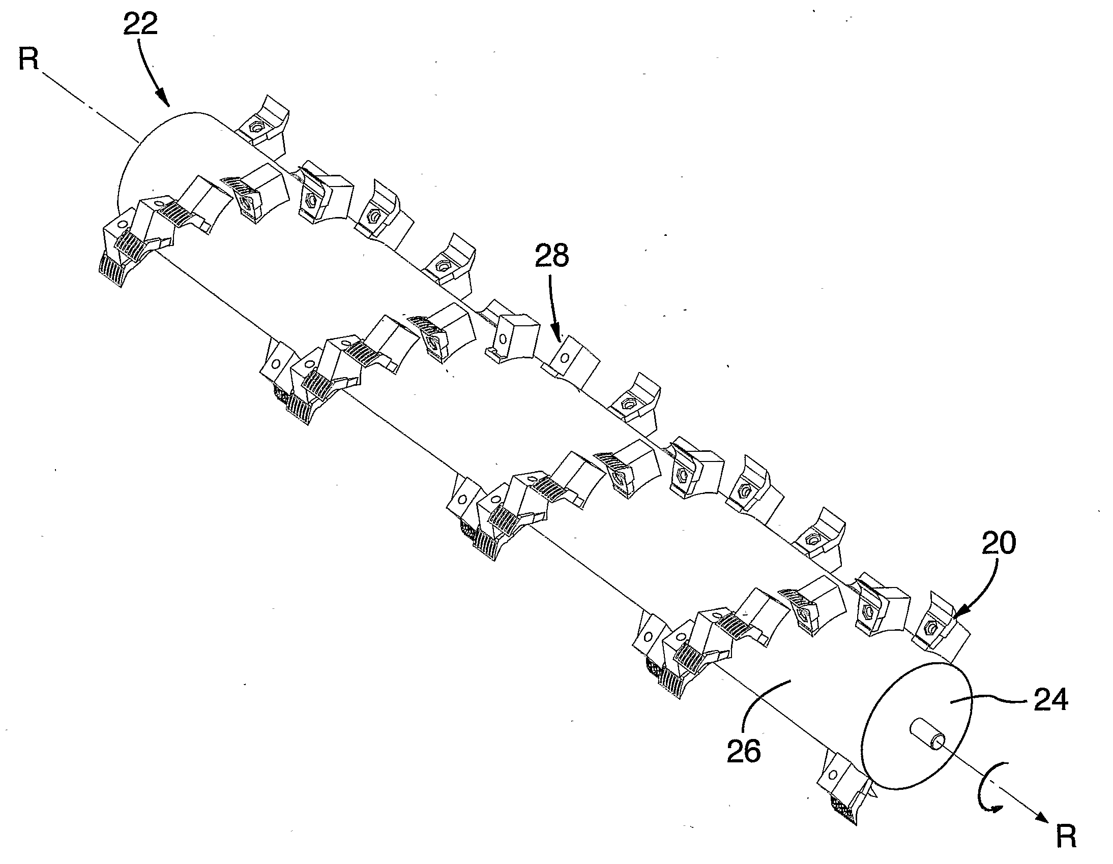
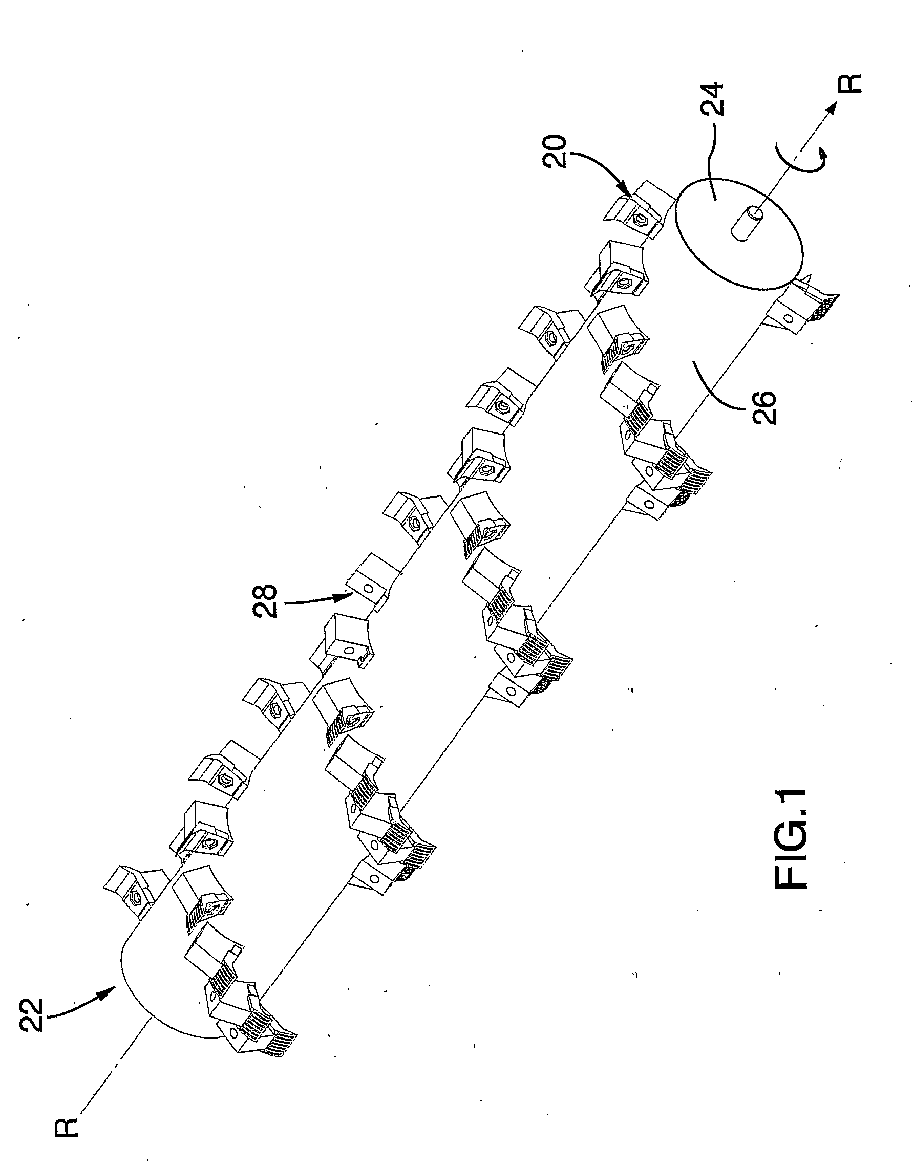
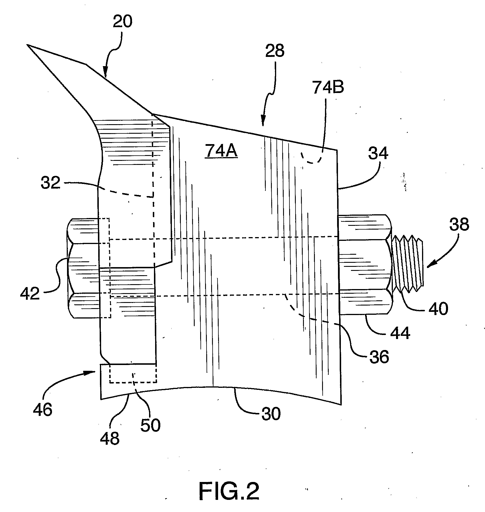
[0035]Referring to FIGS. 1 and 2, there is shown a cutting tooth generally designated with reference numeral 20. Cutting tooth 20 is designed to be mounted onto a cutter head 22 of the type used to cut trees, brush or the like. It will however be appreciated that cutting tooth 20 may be mounted on other types of cutter heads, for instance, those used for shredding paper and / or metal.

[0036]Cutter head 22 has a horizontal drum 24 that is rotatably mountable to a brush cutter (not shown). A drive assembly (not sh...


PUM

PropertyMeasurementUnit
Angleaaaaaaaaaa
Lengthaaaaaaaaaa
Shapeaaaaaaaaaa

Abstract

A cutting tooth is used on a brush cutter head. The cutting tooth includes a cutting portion having a first face and a second face. The first face and the second face cooperate to define a tapering profile terminating in a cutting edge. The first face of the cutting portion carries a plurality of ridges formed thereon to direct cutting debris away from the cutting edge and facilitate passage of the debris along the trailing face when the cutting tooth is in use.

Description

FIELD OF THE INVENTION[0001]The present invention relates to a cutting tooth for use on a brush cutter head.BACKGROUND OF THE INVENTION[0002]Vast felling and mulching operations are often performed with heavy-duty brush cutters. These brush cutters generally consist of cutter heads removably or permanently fixed on self-propelled vehicles.[0003]Heavy-duty brush cutter heads generally have a plurality of blade-type cutting teeth or hammer-type cutting elements, either hingedly or fixedly mounted to the body of a horizontal drum or to the lower surface of a horizontal disc. High velocity rotation of the drum or of the disc causes the cutting elements to shred wood, debris and the like.[0004]Blade-type cutter heads tend to have an advantage over hammer-type cutters in that the dispersion of woodchips during the cutting operation tends to be minimized. This tends to create safer working conditions for workers. U.S. Pat. Nos. 6,321,518, 5,975,167 and 5,642,765 disclose brush-cutter heads...

Claims


Application Information

Patent Timeline
IPC IPC(8): B26D1/12
CPCA01D34/835A01G23/00B02C18/145B02C18/18B23C5/2239B23C2200/361Y10T407/19B26D7/2614B26D2001/0053B26D2001/006Y10T407/2272Y10T407/1934Y10T407/235B26D1/0006
Inventor GAUDREAULT, DANIEL
Owner GYRO TRAC
Learn More