Over-molded thick wall parts

a technology of thick wall parts and injection molding, which is applied in the field of injection molding parts, can solve the problems of increasing the manufacturing cost of the product, increasing the cooling time needed to make the part, and increasing the cost of making the part, so as to achieve substantial time and/or energy saving, improve the aesthetics and/or usefulness of the finished part, and improve the effect of manufacturing efficiency

Inactive Publication Date: 2008-12-04
SABIC INNOVATIVE PLASTICS IP BV
View PDF19 Cites 12 Cited by
  • Summary
  • Abstract
  • Description
  • Claims
  • Application Information

AI Technical Summary

Benefits of technology

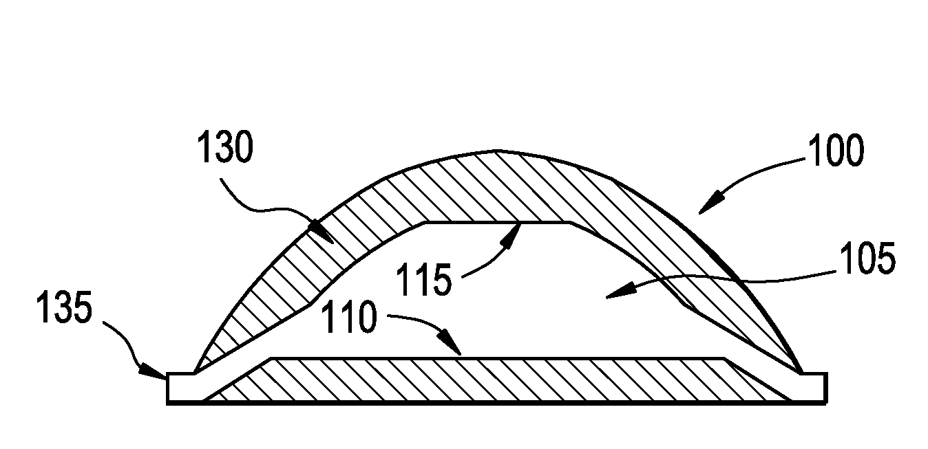
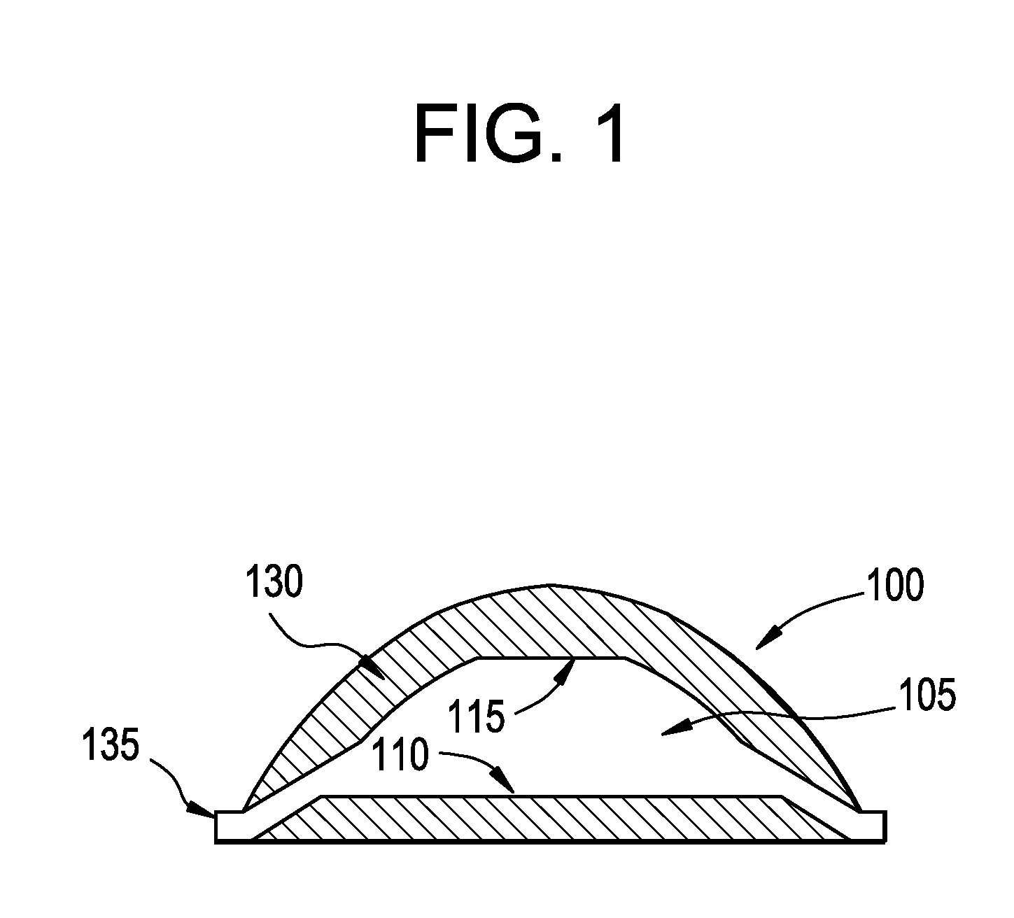
[0009]The present invention addresses the issues associated with the prior art by providing an over-molded thick wall part, an insert used in forming the over-molded thick wall part, and a method of forming over-molded thick wall parts that is faster and / or more energy efficient than prior art methods. The insert includes at least two sides, wherein one of the sides includes a flat surface. With a flat surface, there is a tendency to form sink marks rather than internal shrinkage voids to compensate for the volumetric shrinkage of the resin. Therefore, the flat surface enables the insert to cool without forming voids within the interior of the insert that may adversely affect the aesthetics and / or usefulness of the finished part. The cooled insert is then encompassed within an over-molded outer component to form the thick wall part. By using a two step molding process to form the thick wall part, substantial time and / or energy savings may be achieved as compared to prior art methods of forming thick wall parts. The concepts of the present invention may be used to form a variety of different parts such as ophthalmic lenses, aspheric lenses, projector lenses, cosmetic packaging, handles, plumbing fixtures, gears, pulleys, computer housings, electronics housings and the like.

Problems solved by technology

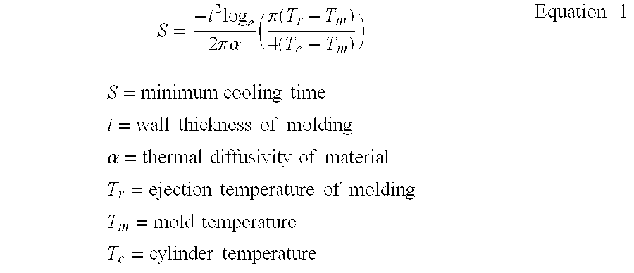
Since the cooling time for a plastic part is exponentially based on the thickness of the part being formed, the thicker the part to be manufactured, the exponentially longer the cooling time needed to make the part, thereby increasing the cost of making the part.
However, as a result of the lower heat transfer rate, the cooling time increases thereby increasing the manufacturing cost of the product due to the increased energy needed to operate at higher mold temperatures and / or the added time needed to cool the thick walled part.

Method used


Image

  • Over-molded thick wall parts
  • Over-molded thick wall parts
  • Over-molded thick wall parts

Examples


Embodiment Construction

[0015]The present invention is more particularly described in the following description and examples that are intended to be illustrative only since numerous modifications and variations therein will be apparent to those skilled in the art. As used in the specification and in the claims, the singular form “a,”“an,” and “the” may include plural referents unless the context clearly dictates otherwise. Also, as used in the specification and in the claims, the term “comprising” may include the embodiments “consisting of” and “consisting essentially of.” Furthermore, all ranges disclosed herein are inclusive of the endpoints and are independently combinable.

[0016]As used herein, approximating language may be applied to modify any quantitative representation that may vary without resulting in a change in the basic function to which it is related. Accordingly, a value modified by a term or terms, such as “about” and “substantially,” may not to be limited to the precise value specified, in ...


PUM

PropertyMeasurementUnit
thicknessaaaaaaaaaa
thicknessaaaaaaaaaa
thicknessaaaaaaaaaa

Abstract

An over-molded thick wall part, an insert used in forming the over-molded thick wall part, and a method of forming over-molded thick wall parts. The insert includes at least two sides, wherein one of the sides includes a flat surface. With a flat surface, there is a tendency to form sink marks rather than internal shrinkage voids to compensate for the volumetric shrinkage of the resin. Therefore, the flat surface enables the insert to cool without forming voids within the interior of the insert that may adversely affect the aesthetics and/or usefulness of the of the over-molded thick wall part. The cooled insert is then encompassed within an over-molded outer component to form the thick wall part. By using a two step molding process to form the thick wall part, substantial time and/or energy savings may be achieved as compared to prior art methods of forming thick wall parts. Depending on the types of materials used to form the insert and the outer component of the thick wall part, various parts may be formed including lenses, handles, housings and the like.

Description

CROSS REFERENCE TO RELATED APPLICATIONS[0001]This application claims priority to U.S. Provisional Application No. 60 / 941,301, filed Jun. 1, 2007, which is hereby incorporated by reference in its entirety.FIELD OF INVENTION[0002]The present invention relates to injection-molded parts and, in particular, to injection-molded, over-molded thick wall parts and methods of making these parts.BACKGROUND OF INVENTION[0003]Thick-walled plastic parts are found in a wide array of applications. Examples of such applications include ophthalmic lenses, aspheric lenses, projector lenses, cosmetic packaging, handles, plumbing fixtures, gears, pulleys, and computer and electronics housings. Thick-walled parts offer a number of advantages such as Strength, performance, aesthetics, and / or ergonomics as compared to thinner-walled parts.[0004]To produce a thermoplastic part using an injection molding process, it is often necessary to heat the material to a molten state and inject the material into a mold...

Claims


Application Information

Patent Timeline
Patent Type & Authority Applications(United States)
IPC IPC(8): B32B27/08
CPCB29C43/146B29C45/14819Y10T428/1352B29C2045/1682B29D11/00009B29C45/16B29C43/14B29D11/00
Inventor KAMIENSKI, JOSEPHMAY, ANDREW W.
Owner SABIC INNOVATIVE PLASTICS IP BV
Why Eureka
Try Eureka