Metallurgical Gas Burner

a gas burner and metallurgical technology, applied in the direction of gaseous fuel burners, combustion types, combustion processes, etc., can solve the problems of increased loading, vibration in the combustion chamber, damage to the lining of steel structures,

Inactive Publication Date: 2008-12-04
HITACHI POWER EURO
View PDF42 Cites 6 Cited by
  • Summary
  • Abstract
  • Description
  • Claims
  • Application Information

AI Technical Summary

Benefits of technology

[0010]Because of the fact that the first swirlers are adjustably arranged within the gas flow cross section, it is possible, if appropriate, to influence the degree of swirling of the flowing combustion gas of low calorific value produced by the first swirlers for adjustment of the tangential velocity component of the gas, and consequently the degree of swirling of the combustible gas flow, even during the operation of a steam generator gas burner. The first swirlers have the effect that the combustible gas flow, initially flowing in the longitudinally axial direction of the gas burner, experiences a deflection in the tangential direction, which imparts a swirl pulse, known as the combustible gas swirl, to the combustible gas flow flowing again in the longitudinally axial direction after leaving the first swirlers. By adjusting the combustible gas swirl, i.e. varying the amount and the degree / inclination of the deflection of the combustible gas flow from its original longitudinally axial direction of flow into a tangential direction of deflection, influence can be brought to bear on the mixing taking place in the mouth region of the burner of the combusible gas of low calorific value with the primary or core air added in the core air tube and the secondary air added radially outside. Depending on the respectively applicable properties of the combustible gas, in particular the respective calorific value of the combustible gas, the first swirlers are set and if applicable adjusted during operation in such a way that optimum burning and flame formation take place, avoiding the occurrence of furnace chamber vibrations. The degree of swirling to be achieved by the position of the first swirlers can in this case both be set, and made to suit the quality of gas to be burned, in a one-off event when the steam generator gas burner is put into operation and be permanently and / or continuously controlled and adapted in accordance with the properties of the combustible material and the combustible gas flow during the operation of the steam generator gas burner.
[0011]In a particularly favourable way, the first swirlers can be arranged adjustably in the gas flow cross section in such a way that the first swirlers are formed as swirl blades extending in the radial direction of the core air tube. As a result, the first swirlers in the form of blades protrude from the outer side of the core air tube into the gas flow cross section, and can therefore be rotatably formed, in particular about the longitudinal axis. Rotation about the longitudinal axis then allows a greater or smaller cross-sectional area of the respective swirl blades, depending on the rotational position, to oppose the direction of flow of the combustible gas flow, and consequently set the combustible gas flow into a different degree of swirling, acting as a flow obstacle and a flow diverting area. For this purpose, the invention provides in a refinement that the first swirlers are rotatably arranged respectively about their longitudinal axis, extending in the radial direction of the core air tube, on the outside of the core air tube.
[0013]Altogether, the arrangement of first swirlers in the gas flow cross section, but also the arrangement of second swirlers in the secondary air flow cross section have the effect of allowing delayed mixing of the combustible gas and the combustion air to be achieved in the outlet region of the steam generator gas burner to the furnace chamber, with the aid of which the ignition can be positioned optimally in each case.
[0014]To assist the delayed mixing of the combustible gas and the combustion air further, the invention is distinguished in a development by a flow directing ring, which is arranged in the mouth region at the end face of the gas tube and has first flow areas, deflecting gas flowing in the gas flow cross section in the direction towards the burner longitudinal axis, and second flow areas, deflecting air flowing in the secondary air flow cross section in the direction away from the burner longitudinal axis. As a result, the secondary air flow is deflected outwards and the combustion gas flow is deflected inwards, and consequently the meeting of the two gases is delayed.
[0015]It is of advantage here if the flow directing ring is arranged axially adjustably on the gas tube, which the invention provides in a refinement.

Problems solved by technology

In the case of gas firing systems, pressure vibrations may occur in the region of the combustion chamber and lead to damage to the lining of the steel structure.
If the combustion produces sufficiently strong pulses with a frequency close to the natural frequency of the combustion chamber, a resonance vibration is created, causing the additional loading.
The varying properties of the fuel have an influence on the formation of the flame and can then in turn lead to combustion chamber vibrations being caused by the combustion.

Method used


Image

  • Metallurgical Gas Burner
  • Metallurgical Gas Burner

Examples


Embodiment Construction

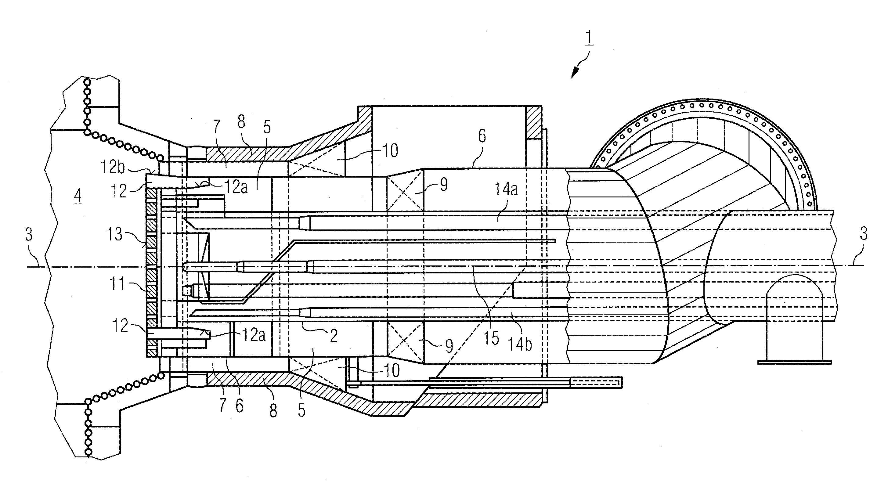
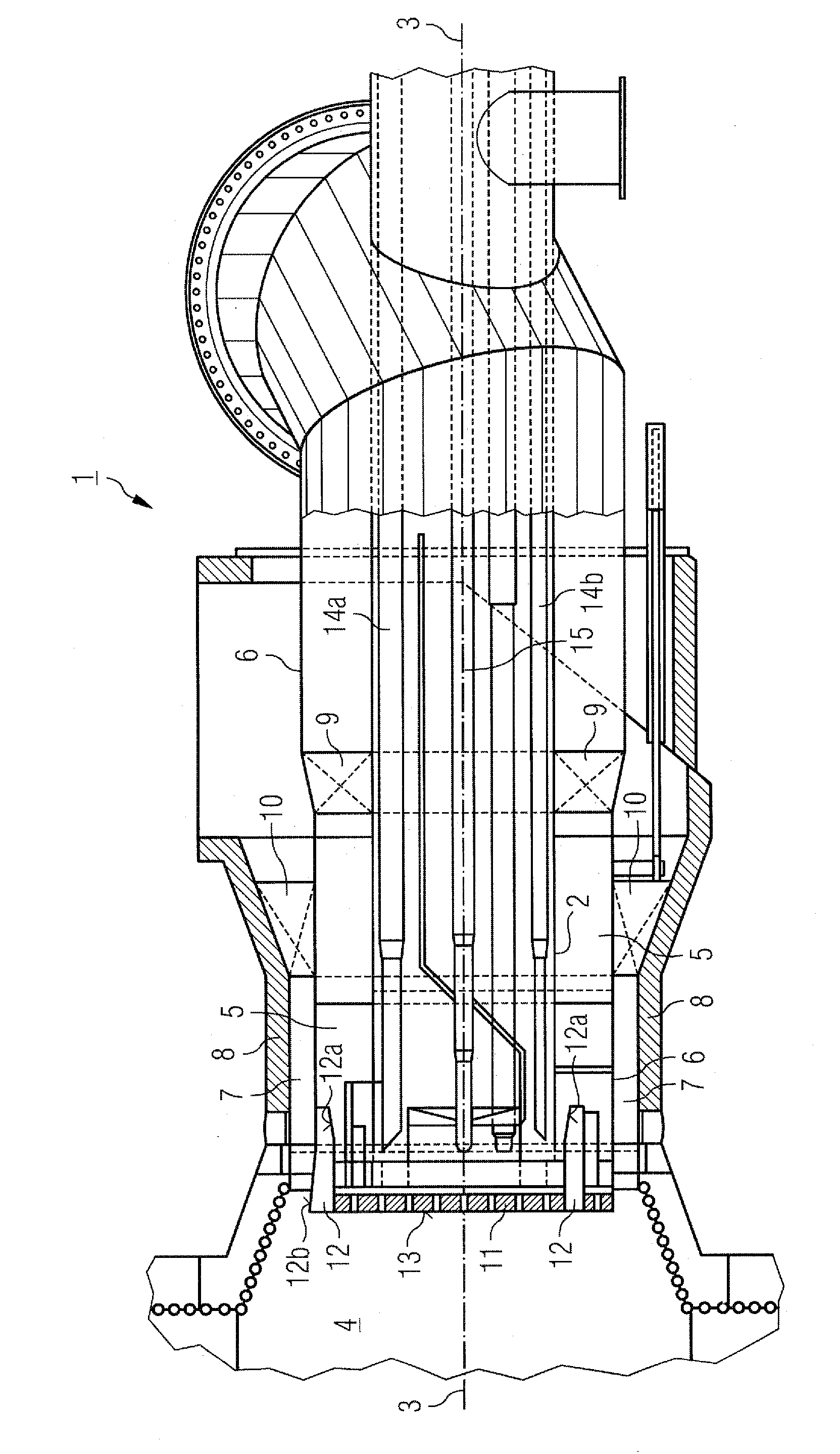
[0019]FIGURE shows in a schematic and partially sectional side view and cross-sectional representation a steam generator gas burner denoted overall by 1, which is designed in the form of what is known as an annular burner. The burner has a core air tube 2, which is arranged in the centre of the steam generator gas burner 1, coaxially around the longitudinal axis 3 of the latter. Combustion air is supplied as core air through the core air tube 2 to the mouth side of the steam generator gas burner 1 that is facing a furnace chamber 4 of a steam generator. Formed around the outside of the core air tube 2, at least in the further end region of the steam generator gas burner 1 on the mouth side, is an annular gas flow cross section 5. This gas flow cross section 5 is delimited on the outside by a gas tube 6, which is arranged coaxially around the core air tube 2. Formed around the gas tube 6 is a further flow region as an annular secondary air flow cross section 7, which is enclosed and ...


PUM


Abstract

A steam generator gas burner for burning gases of low calorific value comprises a core air tube, a gas tube arranged coaxially around the core air tube to form a gas flow cross section, at least one further tube element arranged coaxially around the gas tube to form a secondary air flow cross section and first swirlers being arranged in the gas flow cross section. The first swirlers are adjustably arranged to allow for the steam generator gas burner to adjust to varying properties of the combustible gas, in particular a fluctuating calorific value, while taking into consideration the respective ignition intensity.

Description

PRIORITY CLAIM[0001]This application claims the priority to DE Patent Application Serial No. 10 2007 025 051.9-13, entitled “Metallurgical gas burner,” filed May 29, 2007. The specification of the above-identified application is incorporated herewith by reference.FIELD OF INVENTION[0002]The present invention relates to a steam generator gas burner for burning gases of low calorific value, which comprises a core air tube, a gas tube arranged coaxially around the core air tube to form a gas flow cross section, in particular an annular gas flow cross section, and at least one further tube element arranged coaxially around the gas tube to form a secondary air flow cross section, in particular an annular secondary air flow cross section, wherein first swirlers being arranged in the gas flow cross section.BACKGROUND INFORMATION[0003]When forming gas firing systems for steam generators, gas burners which burn gases of low calorific value are also used. Such gases of low calorific value are...

Claims


Application Information

Patent Timeline
Patent Type & Authority Applications(United States)
IPC IPC(8): F23M9/00
CPCF23D14/24F23D2900/14002
Inventor ZIMMERMANN, BERNHARDMELCHIOR, ROBERTMANGELMANS, KLAUS
Owner HITACHI POWER EURO
Why Eureka
Try Eureka