S-shaped roof vent, ventilated roof employing the same and method of installing the same

a technology of ventilated roof and s-shaped roof, applied in ventilation systems, lighting and heating apparatus, heating types, etc., can solve the problems of numerous different skeletons, difficult to achieve, and difficult to achieve, and achieve the effect of optimizing precision

Inactive Publication Date: 2008-12-04
AIR VENT
View PDF12 Cites 35 Cited by
  • Summary
  • Abstract
  • Description
  • Claims
  • Application Information

AI Technical Summary

Benefits of technology

[0026]It is another object of the invention to provide an improved method of installing generally S-shaped roof vents wherein the sub-flashing of the vent can be installed prior to cutting the ventilation hole in the roof, and wherein the sub-flashing can serve as a template to optimize the precision with which such ventilation hole is made.

Problems solved by technology

Such vents also serve a safety function, as excessive heat can result in damage to the roof, and could potentially cause a fire.
This can be particularly difficult where, for example, the tiles of the roof have a relatively complex shape such as, for example, the general S-shape which is commonly associated with Spanish tiles.
This disadvantageously requires numerous different skeletons to be made for each particular type of roof application.
Such spacing presents the possibility for debris, animals, moisture, or other matter to undesirably enter under the vent cap, through the space between the cap and the base.
In addition to the foregoing, there are also a number of unique problems with the manner in which such vents must be installed.
Such problems are, in large part, related to the construction of the vents.
However, the roof might not be tiled until several days or even weeks later.
Accordingly, the aforementioned matter, such as moisture, and relatively small debris can undesirably enter the building through the primary vent.
It is also difficult to size and position the hole in the roof decking precisely so as to match the hole of the primary vent in order to maximize the net flow area and ventilation through the vent.

Method used


Image

  • S-shaped roof vent, ventilated roof employing the same and method of installing the same
  • S-shaped roof vent, ventilated roof employing the same and method of installing the same
  • S-shaped roof vent, ventilated roof employing the same and method of installing the same

Examples


Embodiment Construction

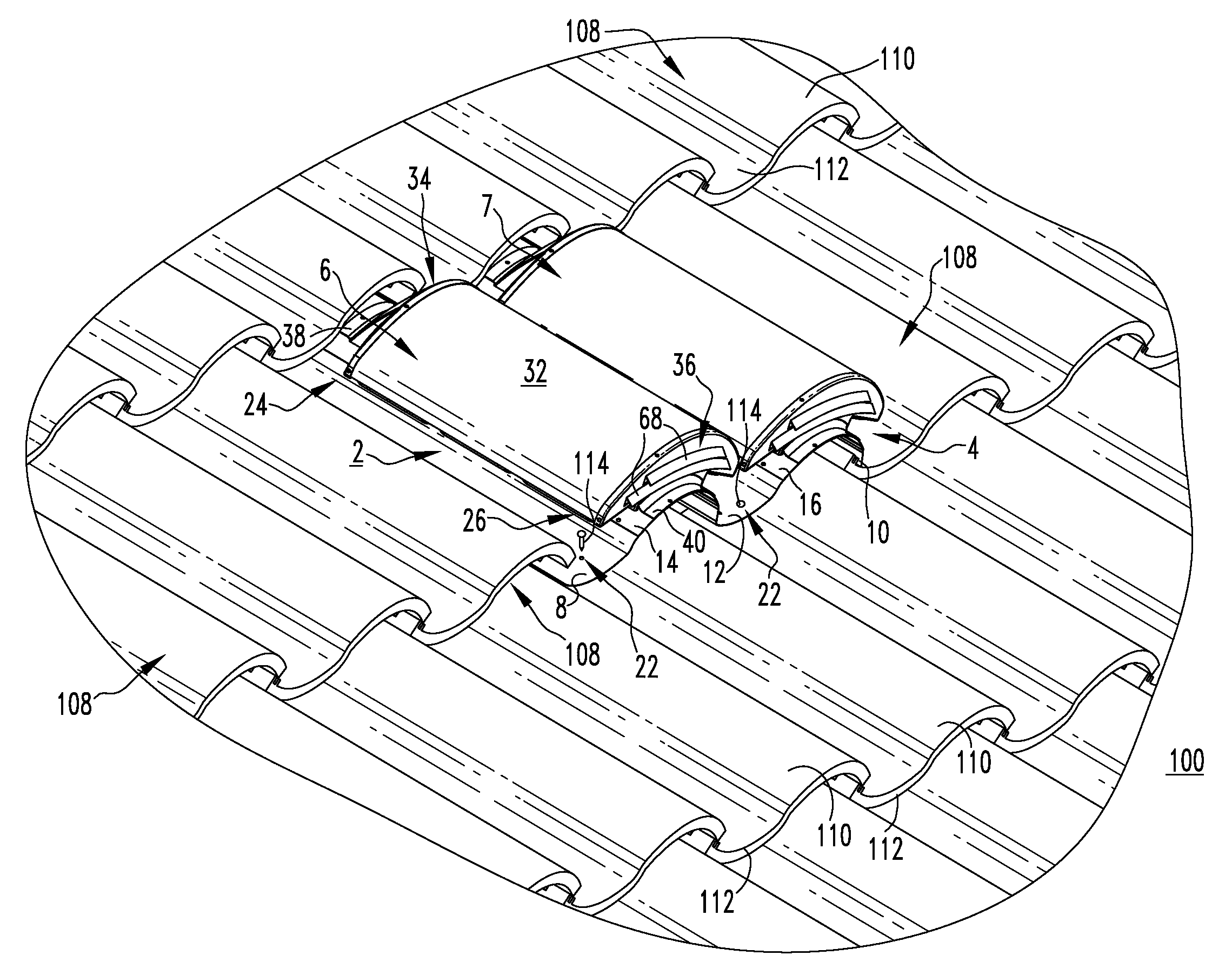
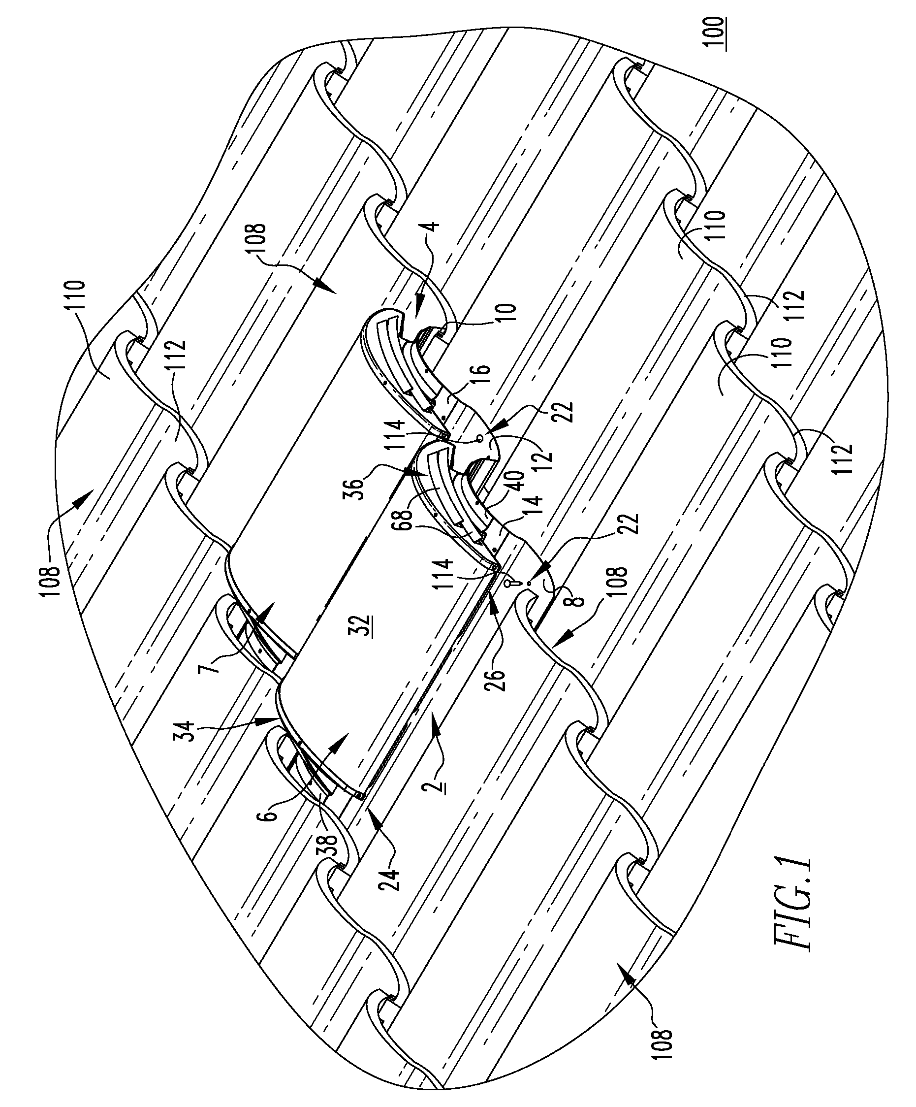
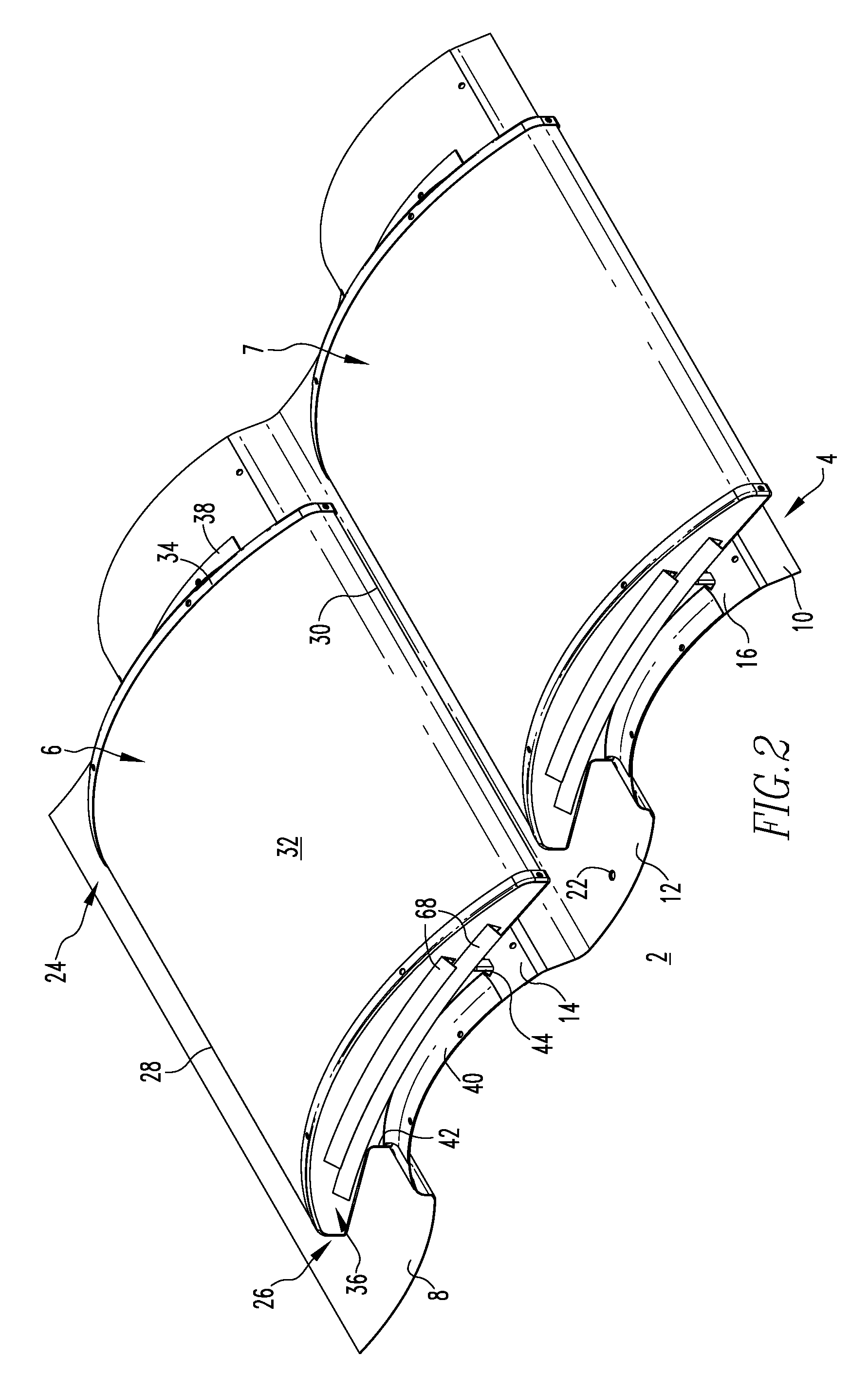
[0035]For purposes of illustration, embodiments of the invention will be described as applied to roof vents in which a segment of the vent comprising one concave section and one convex section of the base assembly and a single cap member coupled to the convex section, has a generally S-shaped cross-sectional profile when viewed from an end elevation perspective. It will, however, become apparent that they could also be applied to roof vents having a cross-sectional profile which is not S-shaped such as, for example and without limitation, an arcuate shape which does not resemble the letter S.

[0036]Directional phrases used herein, such as, for example, left, right, front, back, top, bottom and derivatives thereof, relate to the orientation of the elements shown in the drawings and are not limiting upon the claims unless expressly recited therein.

[0037]As employed herein, the terms “fastener” and “fastening mechanism” refer to any known or suitable connecting, tightening or securing m...


PUM

PropertyMeasurementUnit
angleaaaaaaaaaa
angleaaaaaaaaaa
areaaaaaaaaaaa

Abstract

A generally S-shaped vent is provided for a roof including a substructure having at least one ventilation hole and being covered by a plurality of tiles. The tiles form a finish layer having peaks and valleys. The vent includes a base assembly having a number of flange members and at least one venting member with a vent aperture. The flange members are coupled to the roof substructure at or about the ventilation hole. At least one cap member is coupled to the base assembly, overlaying the vent aperture and including an upslope end, a downslope end, first and second sides, and an arcuate portion extending between the first and second sides. First and second louvered portions of the first and second sides of the cap member provide a ventilating passageway through the vent. The vent substantially conforms to the peaks and valleys of the finish layer of the roof.

Description

BACKGROUND OF THE INVENTION[0001]1. Field of the Invention[0002]The invention relates generally to vents and, more particularly, to generally S-shaped roof vents for ventilating the roof of a structure, such as a building, while conforming to the general shape of the finish layer of the roof. The invention also relates to ventilated roofs. The invention further relates to a method of installing roof vents.[0003]2. Background Information[0004]Vents are commonly employed on the roofs of structures, such as residential buildings, commercial buildings and other structures, in order to exhaust air from beneath the roof (e.g., from an attic space) into the surrounding atmosphere.[0005]For example, a variety of passive roof vents have been employed at various locations on building roofs in an attempt to release heat which can undesirably build up and become trapped under the roof. Passive vents provide an air passageway for such hot air to be exhausted from the roof, and thereby help to ma...

Claims


Application Information

Patent Timeline
Patent Type & Authority Applications(United States)
IPC IPC(8): F24F7/02
CPCE04D1/30E04D13/17Y10T29/53F24F7/02E04D2001/309
Inventor ROBINSON, LARRY D.
Owner AIR VENT
Why Eureka
Try Eureka