
Portable video communication system

Active Publication Date: 2008-12-04
MONUMENT PEAK VENTURES LLC
View PDF17 Cites 73 Cited by
  • Summary
  • Abstract
  • Description
  • Claims
  • Application Information

AI Technical Summary

Benefits of technology

[0014]The present invention aims to provide improved apparatus for video communication with a portable video system that provides improved video quality and is suitable for use in portable devices.

Problems solved by technology

Conventional systems are typically large, fixed in location, have a restricted ability to cope with changes in scene focus, and do not necessarily provide natural communication.
Moreover, conventional designs do not take advantage of available, portable display and capture systems such as are found in cellular telephones and similar hand-held devices.
Although such two-way video communication systems have been produced and used for high-end teleconferencing and other two-way video communications applications, there are some significant practical drawbacks for incorporation in a portable and hand-held video communication systems.
However, numerous problems continue to exist that are peculiar to the hand-held environment, such as image quality, ease of use, security, and privacy, that have not yet been adequately addressed.
One relevant problem for hand-held communication devices, are their inability to compensate for observer motion or vibration, poor image capture angles, and changes in the field of view.
However, neither Carpenter or Yu address the problem of poor capture angle produced by the low hand position (see FIG. 12) that is commonly used by people when looking at the handheld display of a mobile phone camera or other portable imaging and display device.
This approach does not address poor capture angle or image shake produced by hand jitter as is commonly encountered when the portable imaging and display device is operated with one hand while the user is in motion.
Additionally the method disclosed by Bober does not suggest alteration of the background to improve privacy or reduce data transmission rate.
However, this approach does not provide a sufficiently versatile approach wherein the user would like to show his face during video communication without showing the background from the environment or would like to select a different background that is more suitable for the recipient of the image.
While both Kyle and Akiyama disclose useful techniques for verification of the identity of a user, neither Kyle nor Akiyama teach simplified techniques that would be implementable in a hand-held communication device.
In addition, Kyle and Akiyama do not teach the use of a portable imaging and display device as a versatile, self-contained personal security system.
Portable imaging and display devices or systems require special solutions due to their small size, limited capabilities, inherent problems, and high mobility.
Conventional solutions do not address the problems of vibration and capture angle induced by one-handed operation of a portable imaging device nor do these solutions adequately address the problems of privacy, background suitability, or security for effective communication.

Method used


Image

  • Portable video communication system
  • Portable video communication system
  • Portable video communication system

Examples


Embodiment Construction

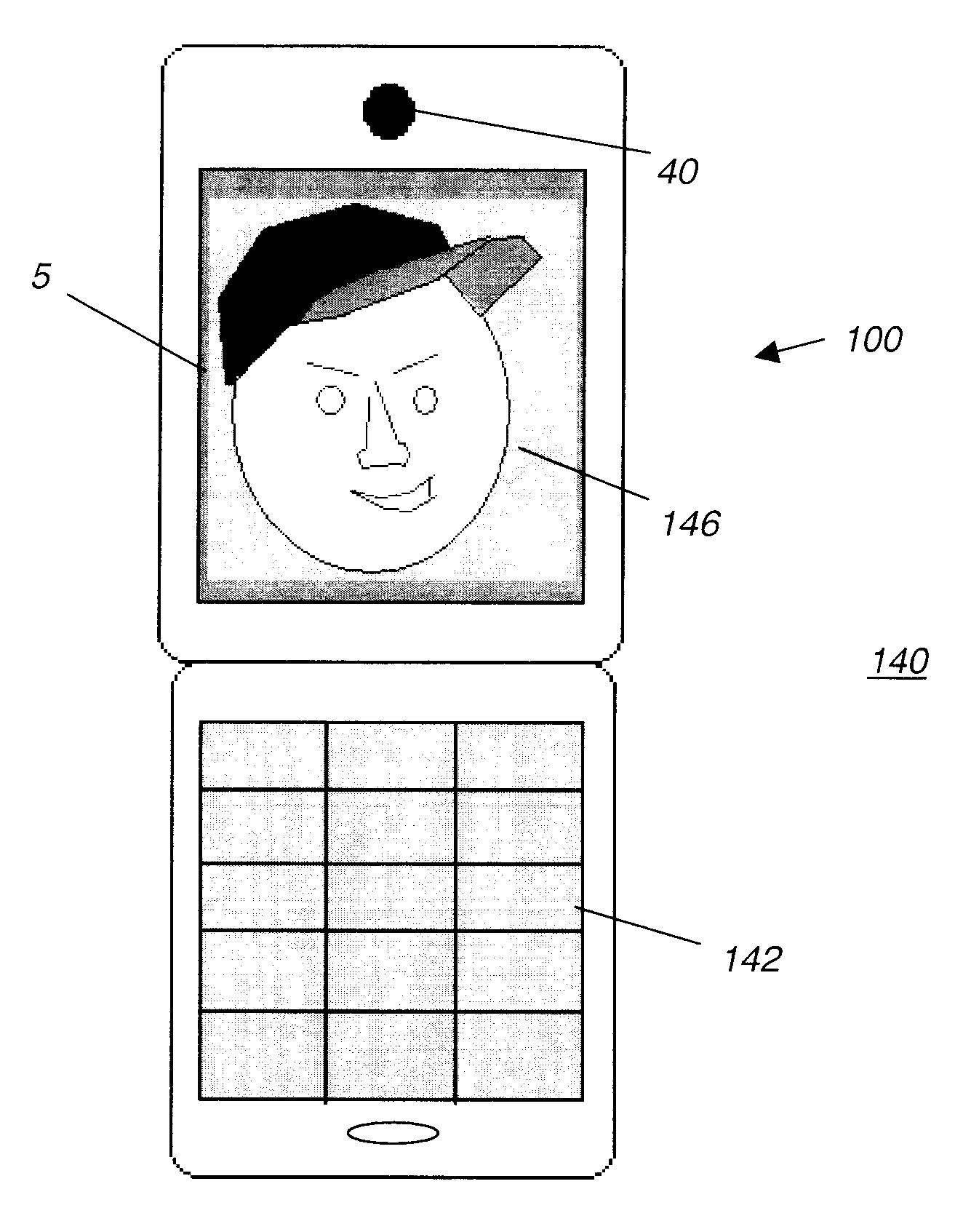
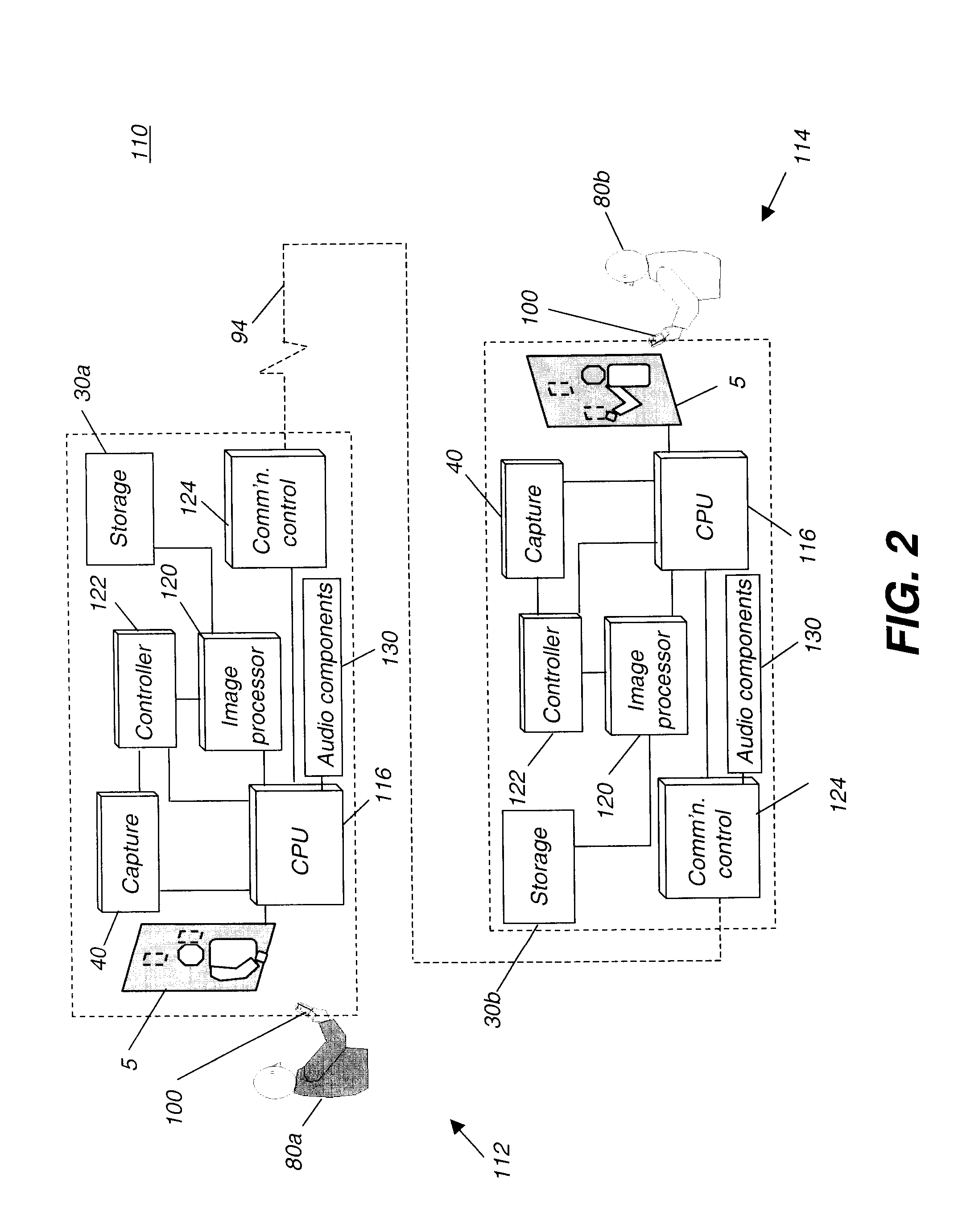
[0055]Referring to FIG. 2 there is illustrated a two-way communication system 110 for hand-held portable devices for wireless communication between an user 80a using a hand-held portable wireless display and digital capture device 100 made in accordance with the present invention at a first site 112 and an user 80b at a second site 114 remote from the first site using a second hand-held portable wireless display and digital capture device 100 made in accordance with the present invention. In the embodiment illustrated in FIG. 2, hand-held portable wireless display and digital capture device 100 comprises a cell phone, however, the present invention is not so limited. Hand-held portable wireless display and digital capture device 100 may comprise any hand held device capable of wireless communication that can capture and display images, for example but not limited to digital cameras and personal digital assistants (PDAs). The hand-held portable wireless display and digital capture de...


PUM


Abstract

A method and device for adapting a display image on a hand-held portable wireless display and digital capture device. The device includes a camera for capturing a digital video and / or still image of a user, means for adjusting the captured digital image in response to poor image capture angle of said image capture device so as to create a modified captured digital image; and means for transmitting said modified captured digital image over a wireless communication network to a second hand-held portable wireless display and digital capture device.

Description

FIELD OF THE INVENTION[0001]The present invention generally relates to two-way video communication systems and more particularly relates to a portable two-way video communication system that is adapted to hand-held video communication devices.BACKGROUND OF THE INVENTION[0002]Two-way video systems are available that include a display and camera in each of two locations connected by a communication channel that allows communication of video images and audio between two different sites. Originally, such systems relied on a setup at each site of a video monitor to display a remote scene and a separate video camera, located on or near the edge of the video monitor, to capture a local scene, along with microphones to capture the audio and speakers to present the audio thereby providing a two-way video and audio telecommunication system between two locations. Conventional systems are typically large, fixed in location, have a restricted ability to cope with changes in scene focus, and do n...

Claims


Application Information

Patent Timeline
IPC IPC(8): H04M1/00
CPCH04N7/141H04N5/23248H04N5/23254G06K9/00228H04N21/41407H04N21/4223H04N5/272H04N5/2621G06V40/161H04N23/68H04N23/6811H04N7/147
Inventor BORDER, JOHN N.COK, RONALD S.ENGE, AMY D.KURTZ, ANDREW F.MANICO, JOSEPH A.SCHILLING-BENZ, LYNNSTUBLER, PETER O.WILLIAMS, FRANCES C.
Owner MONUMENT PEAK VENTURES LLC
Learn More