Final reduction gear device

a technology of gear device and gear shaft, which is applied in the direction of gearing details, gearing, transportation and packaging, etc., can solve the problems of noise generation and efficiency degradation, and achieve the effects of improving positioning precision and support rigidity, aligning performance and support rigidity of internal gear relative, and improving meshing precision

Inactive Publication Date: 2008-12-04
SUBARU CORP
View PDF3 Cites 5 Cited by
  • Summary
  • Abstract
  • Description
  • Claims
  • Application Information

AI Technical Summary

Benefits of technology

[0012]According to the second invention, the internal gear is fixed to the case main body after improving the positioning precision and support rigidity thereof by fitting the fitting portion thereof to the spigot portion of the holding member. Thus, the alignment performance and support rigidity of the internal gear relative to the left and right output shafts and a planetary gear can be further improved, enabling an improvement in meshing precision and a reduction in tooth contact noise among the various gears of the speed reduction mechanism portion.
[0013]According to the final reduction gear device of the present invention, the support rigidity of a bevel ring gear and an internal gear can be improved without increasing the size of a case main body, and therefore an efficient final reduction gear device that is capable of reducing tooth bearing defects among various gears during power transmission and reducing alignment defects in a planetary gear mechanism can be provided.

Problems solved by technology

However, although the compactness of the final reduction gear device is increased, the bevel ring gear (4) and an internal gear (9) of the speed reduction mechanism portion (3) are supported in a cantilevered fashion, and therefore, unless the support rigidity of the bevel ring gear (4) and the internal gear (9) is improved, the rotation of the bevel ring gear (4) becomes unstable during power transmission, leading to tooth bearing defects, defects in the alignment of a planetary gear (10) of the speed reduction mechanism portion (3) and so on, a degradation in efficiency, and the generation of noise.

Method used


Image

  • Final reduction gear device
  • Final reduction gear device
  • Final reduction gear device

Examples


Embodiment Construction

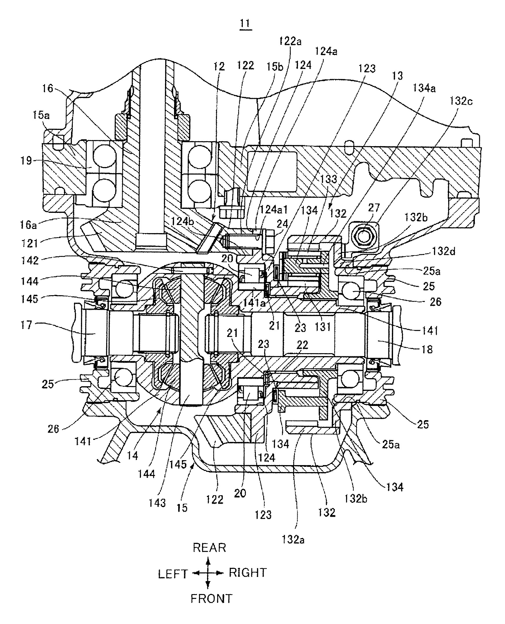
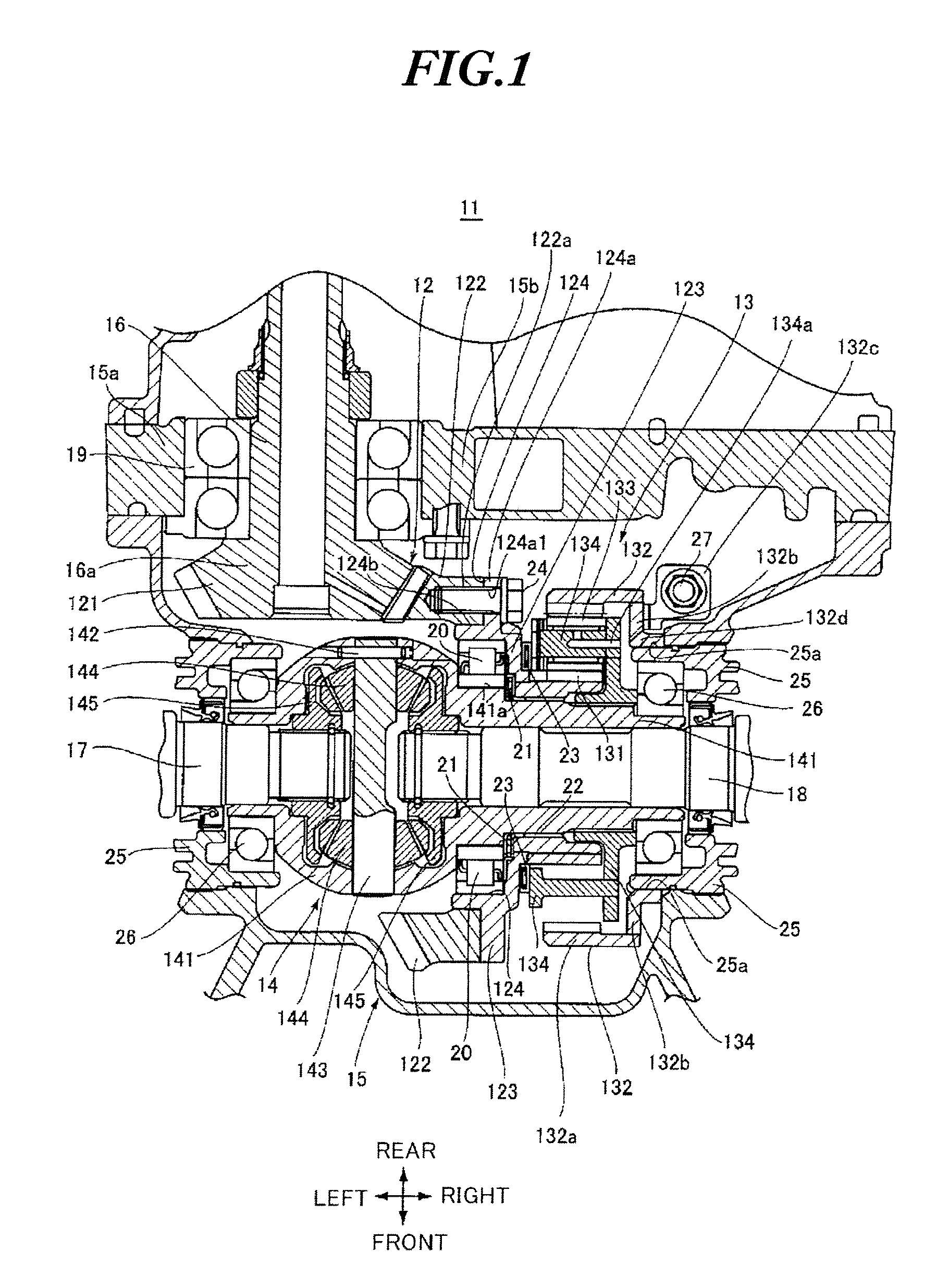
[0020]A final reduction gear device according to an embodiment of the present invention will be described in detail below with reference to FIGS. 1 and 2. FIG. 1 is a sectional view showing an embodiment of the final reduction gear device, and FIG. 2 is a side view of FIG. 1.

[0021]As shown in FIG. 1, a final reduction gear device 11 according to the present invention comprises an orthogonal axis gear 12, a speed reduction mechanism portion 13 employing a planetary gear, and a differential gear mechanism portion 14.

[0022]Note that FIGS. 1 and 2 show a state in which the final reduction gear device 11 is disposed in a transmission case 15 serving as a case main body that is provided as a continuation of a longitudinal engine, not shown in the drawings. In FIG. 1, the lower side and upper side of the paper surface indicate the front and rear, respectively, while in FIG. 2, the right side of the drawing indicates the front side.

[0023]The orthogonal axis gear 12 comprises a bevel pinion ...


PUM


Abstract

A final reduction gear device including an orthogonal axis gear and a speed reduction mechanism portion employing a planetary gear is provided. A radial bearing, more specifically a cylindrical roller bearing, having a large radial load capacity is disposed between a bevel ring gear of the orthogonal axis gear and a differential case. A thrust bearing, more specifically a thrust ball bearing or a thrust roller bearing, having a large axial load capacity is disposed between an axial end portion of a sun gear, and an inner race side of the radial bearing and the side of a fitting portion of the differential case, to which the inner race is fitted. A thrust bearing, more specifically a thrust ball bearing or a thrust roller bearing, having a large axial load capacity is disposed between the bevel ring gear and a planetary carrier of the speed reduction mechanism portion.

Description

CROSS-REFERENCE TO RELATED APPLICATIONS[0001]The disclosure of Japanese Patent Application No. 2007-146986 filed on Jun. 1, 2007 including the specification, drawings and abstract is incorporated herein by reference in its entirety.BACKGROUND OF THE INVENTION[0002]1. Field of the Invention[0003]The present invention relates to a final reduction gear device, and more particularly to a final reduction gear device comprising an orthogonal axis gear, and a speed reduction mechanism portion employing a planetary gear.[0004]2. Description of the Related Art[0005]In an orthogonal axis gear of a conventional final reduction gear device, as shown in FIG. 3, a skew gear, or in other words a so-called hypoid gear, is used (see Japanese Unexamined Patent Application Publication 2007-40339, for example), but as the offset of the hypoid gear increases, friction during a low load period increases. Therefore, as shown in FIG. 4, the efficiency of the final reduction gear device may be improved by u...

Claims


Application Information

Patent Timeline
Patent Type & Authority Applications(United States)
IPC IPC(8): F16H48/06B60K17/16F16H57/021F16H57/037F16H57/038F16H57/039
CPCB60K17/16F16H1/28F16H48/08F16H57/021
Inventor HIRASE, HIROMI
Owner SUBARU CORP
Why Eureka
Try Eureka