Novel Packaging Solution for Highly Filled Phase-Change Thermal Interface Material

a technology of thermal interface material and packaging solution, which is applied in the direction of packaging, liquid handling, transportation and packaging, etc., can solve the problems of affecting easy damage or improper application, and well-known impede the flow of heat, so as to facilitate the transfer of heat, improve reliability, and put in position quickly and easily

Inactive Publication Date: 2008-12-11
RAUCH ROBERT A
View PDF16 Cites 24 Cited by
  • Summary
  • Abstract
  • Description
  • Claims
  • Application Information

AI Technical Summary

Benefits of technology

[0015]Once the layer of material is exposed, the same is deposited directly upon the substrate, namely, that portion of the heat sink defining the thermal interface. Such application will typically involve merely placing the exposed layer of material at a target site upon a substrate, namely, the thermal interface, and thereafter rapidly pulling the tape adhesively bound to the top layer away from the substrate. In a more highly preferred method, the system will utilize a piece of tape extending over the top liner and layer of material disposed there underneath with the extended portion of tape being utilized to first tape the exposed layer of material at a target site upon the substrate. By gently pulling the tape upward, the top liner adhesively bound thereto will peal away from the layer of material, with the material staying at rest and remaining adhered to the interface due to its much greater inertia than the tape and top liner. In this regard, pulling on the tape which is adhesively attached to the interface creates a resistive force opposite to the pull. At the point where the adhesive stops, the pull continues and the resistive force stops, resulting in a rate of change of acceleration being imparted to the top liner through the tape. The resulting acceleration of the top liner is not transferred to the material due to incomplete adhesion between the material and the top liner. The material stays at rest and remains on the interface surface while the top liner is removed for final assembly. As a consequence, the layer of material is precisely and uniformly put into position quickly and easily, and further, advantageously dispenses with the need for any type of substrate to properly position such material.
[0016]It is therefore an object of the present invention to provide a packaging system, method of packaging, and method of applying a layer of material at a desired location upon a substrate, and in particular a layer of phase change material operative to facilitate the transfer of heat from a heat-dissipating component to a heat sink, that is exceptionally more reliable, of simple construction, and substantially faster and easier to utilize than prior art packaging and application techniques.
[0017]Another object of the present invention is to provide packaging system, method of packaging, and method of applying a layer of material at a desired location upon a substrate, and in particular a layer of phase change material operative to facilitate the transfer of heat from a heat-dissipating component to a heat sink, that provides for better product protection and substantially conserves the amount of material utilized to facilitate the transfer of heat than prior art practices.
[0018]Still further objects of the present invention are to provide a packaging system, method of packaging, and method of applying a layer of material at a desired location upon a substrate, and in particular a layer of phase change material operative to facilitate the transfer of heat from a heat-dissipating component to a heat sink, that is of simple construction, can be readily implemented utilizing known manufacturing techniques and materials, and substantially minimizes labor associated with the application of heat-transfer compositions to the interface between a heat-dissipating component and heat sink coupled therewith.

Problems solved by technology

To the extent heat is not removed, such electronic componentry will operate sub-optimally and can become damaged, sometimes irreparably.
Despite the ideal properties of phase change materials to facilitate the transfer of heat, however, are drawbacks associated with the ability to package, ship and apply such materials at the interface between the electronic component and heat sink to be coupled therewith.
Specifically, most phase change materials are formed to have as minimal thickness as possible in order to maximize the transfer of heat and thus are very fragile.
Moreover, due to the phase change property of such materials, the same are easily torn or ablated during application, and thus can be easily damaged or improperly applied.
The use of a substrate, however, is well-known to impede the flow of heat by introducing additional thickness at the interface, as well as by introducing a separate layer of material that extends across the path of heat flow.

Method used


Image

  • Novel Packaging Solution for Highly Filled Phase-Change Thermal Interface Material
  • Novel Packaging Solution for Highly Filled Phase-Change Thermal Interface Material

Examples


Embodiment Construction

[0025]The detailed description set forth below is intended as a description of the presently preferred embodiment of the invention, and is not intended to represent the only form in which the present invention may be constructed or utilized. The description sets forth the functions and sequences of steps for constructing and operating the invention. It is to be understood, however, that the same or equivalent functions and sequences may be accomplished by different embodiments and that they are also intended to be encompassed within the scope of the invention.

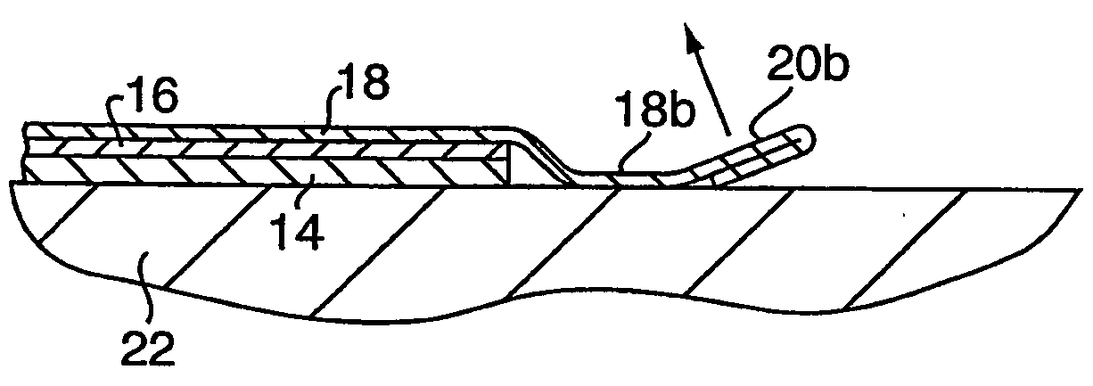
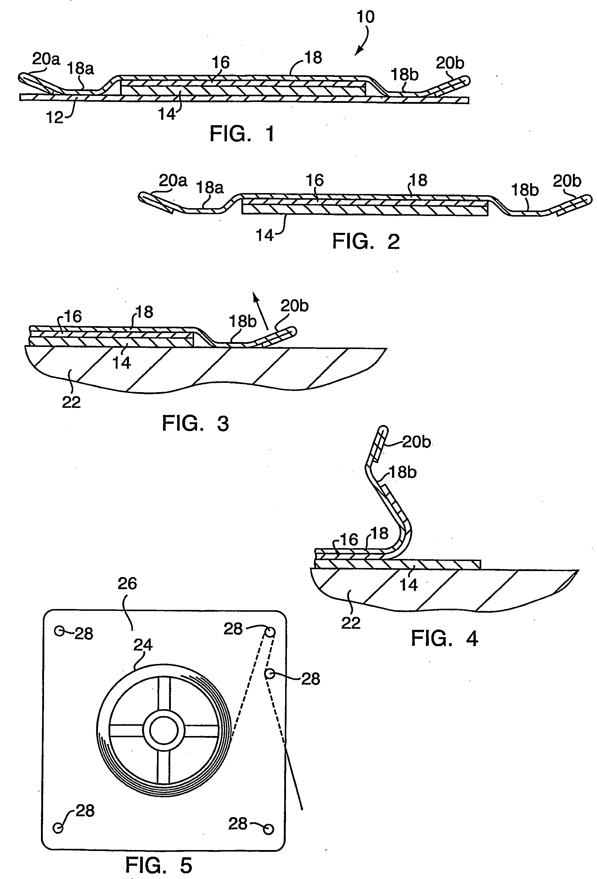
[0026]Referring now to the figures, and initially to FIG. 1, there is shown a preferred packaging system 10 for a thin layer of material 14, the latter preferably comprising a single layer or film of thermally-conductive material having phase change properties. In this regard, it is expressly contemplated that packaging 10 will be particularly well suited to facilitate the manufacturing, shipping, handling and ultimate applicat...


PUM


Abstract

A packaging system, packaging method and method of depositing a thin layer of material at a desired location upon a substrate, and in particular a layer of thermally-conductive phase change material at the interface between a heat-dissipating component and heat sink coupled therewith. The packaging comprises a thin layer of material sandwiched between a first base liner and a second top liner. A segment of tape is adhesively bound to the top liner and preferably includes a graspable portion, such as a tab, to enable the same to pull the top liner away from the material to thus leave the layer of material deposited upon the substrate.

Description

CROSS-REFERENCE TO RELATED APPLICATIONS[0001]Not ApplicableSTATEMENT RE: FEDERALLY SPONSORED RESEARCH / DEVELOPMENT[0002]Not ApplicableBACKGROUND OF THE INVENTION[0003]Compositions, systems and methods for facilitating the transfer of heat from a heat dissipating component to a heat sink are well-known in the art. Exemplary of such compositions, methods and systems include those disclosed and claimed in U.S. Pat. No. 5,904,796, issued May 18, 1999, entitled ADHESIVE THERMAL INTERFACE & METHOD OF MAKING THE SAME; U.S. Pat. No. 5,912,805, issued Jun. 15, 1999, entitled THERMAL INTERFACE WITH ADHESIVE; U.S. Pat. No. 6,483,707, issued Nov. 19, 2002, entitled HEAT SINK & THERMAL INTERFACE HAVING SHIELDING TO ATTENUATE ELECTROMAGNETIC INTERFERENCE; U.S. Pat. No. 6,616,999, issued Sep. 9, 2003, entitled PREAPPLIABLE PHASE CHANGE THERMAL INTERFACE PAD; U.S. Pat. No. 6,652,705, issued Nov. 25, 2003, entitled GRAPHITIC ALLOTROPE INTERFACE COMPOSITION AND METHOD OF FABRICATING THE SAME; and U.S....

Claims


Application Information

Patent Timeline
Patent Type & Authority Applications(United States)
IPC IPC(8): B65B7/28
CPCH01L21/6835H01L23/427H01L2924/3025H01L2924/0002H01L2924/00
Inventor RAUCH, ROBERT A.
Owner RAUCH ROBERT A
Why Eureka
Try Eureka