Helical part manufacturing apparatus and control method thereof

a manufacturing apparatus and helical part technology, applied in the field of manufacturing techniques of helical parts, can solve the problems of thermal deformation on the cutting surface, reduced production efficiency, cost and machine installation locations, etc., and achieve the effect of improving production efficiency, low cost and processing the outer shape of helical parts

Inactive Publication Date: 2008-12-11
ITAYA SEISAKUSHO
View PDF11 Cites 36 Cited by
  • Summary
  • Abstract
  • Description
  • Claims
  • Application Information

AI Technical Summary

Benefits of technology

[0024]According to the invention, it is possible to cut a helical part and flatten the surface of the part's end portions without the use of laser beams or jet water as cutting unit.
[0025]Furthermore, the invention enables not only cutting of a helical part but also easily processing the outer shape of a helical part.
[0026]By virtue of the above fe

Problems solved by technology

The necessity of the differently provided grinding machine has been causing problems in terms of costs and machine installing locations.
Also, the grinding process necessary in addition to the spring manufacturing process has been causing reduced production efficiency.
However, according to aforementioned Ja

Method used


Image

  • Helical part manufacturing apparatus and control method thereof
  • Helical part manufacturing apparatus and control method thereof
  • Helical part manufacturing apparatus and control method thereof

Examples


first embodiment

Modification of First Embodiment

[0106]In the above-described first embodiment, the discoid grindstone 31 of the grindstone tool unit 30 is used for cutting the helicoid and grinding the end portions of the helicoid. In the modification, the grindstone tool unit 30 is adapted as grinding unit for processing the outer shape of the helical part.

[0107]FIGS. 9A to 9C are respectively a front elevation, a side elevation, and a cross-section showing an outer shape of a helical part manufactured by the manufacturing apparatus according to the first embodiment. FIGS. 10A to 10C are views showing an outer shape of a helical part which is processed by the grindstone tool unit according to the embodiment.

[0108]The helical part 2 shown in FIGS. 9A to 9C is an antenna, which is configured by helically winding a wire having a rectangular cross-section, and is mounted to a wireless communication device such as a mobile-phone.

[0109]By controlling the operation of respective units 10 to 40 shown in F...

second embodiment

[0112]In the above-described first embodiment, the helicoid cutting is performed using only the grindstone tool unit 30. However in the second embodiment, a helicoid cutting is performed by cooperatively operating the grindstone tool unit 30 and laser unit 50.

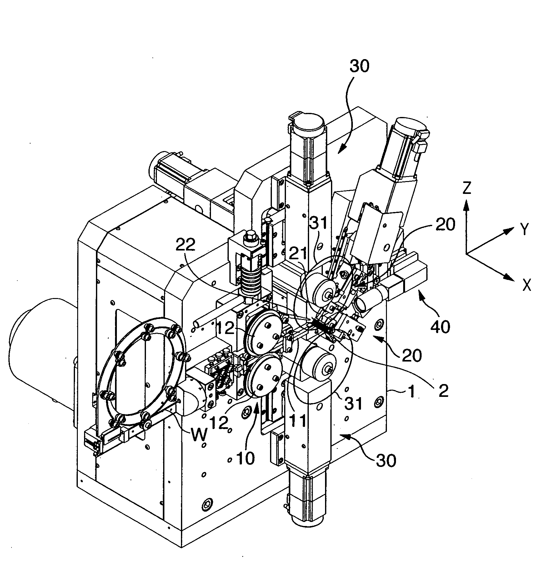
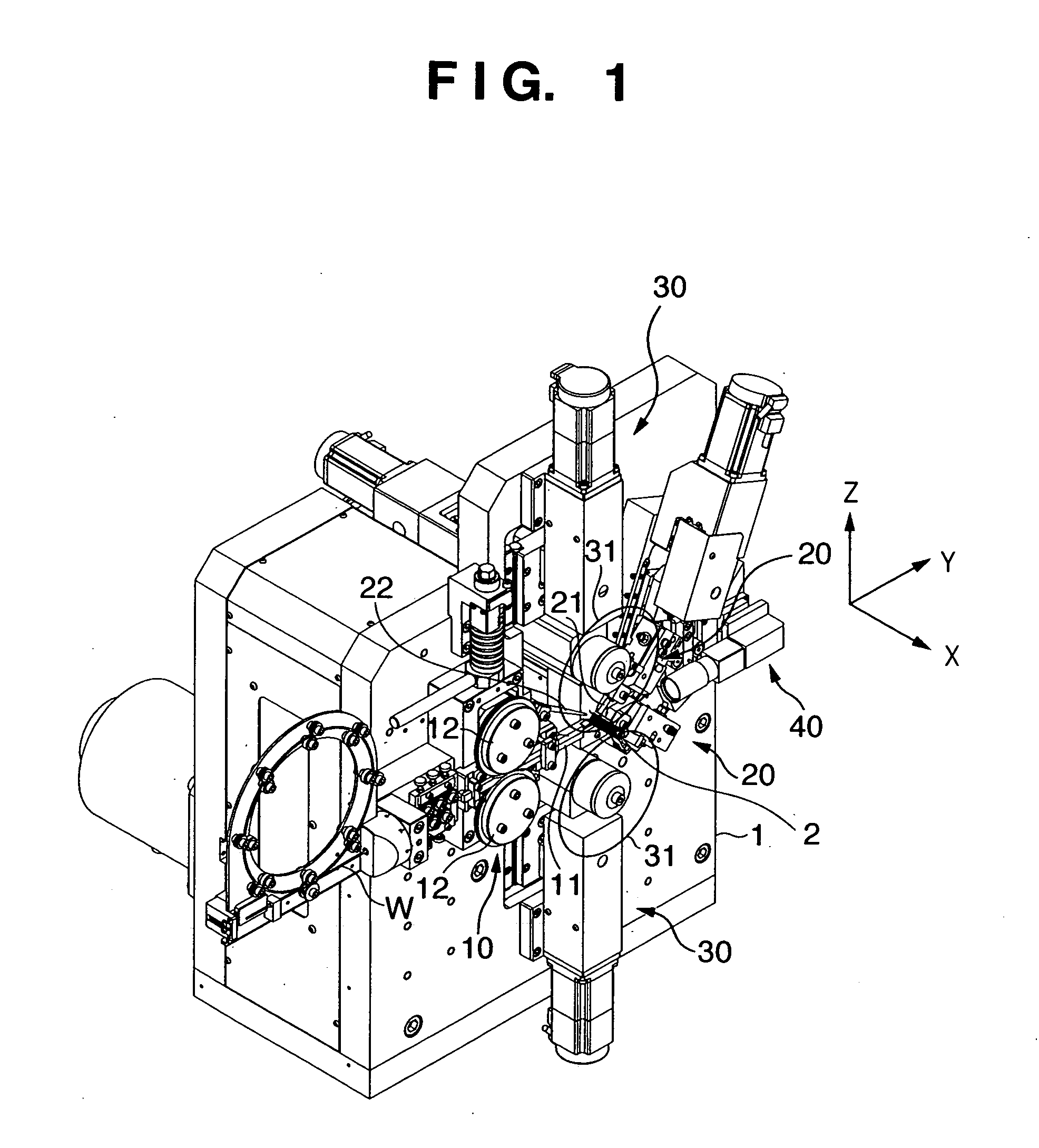
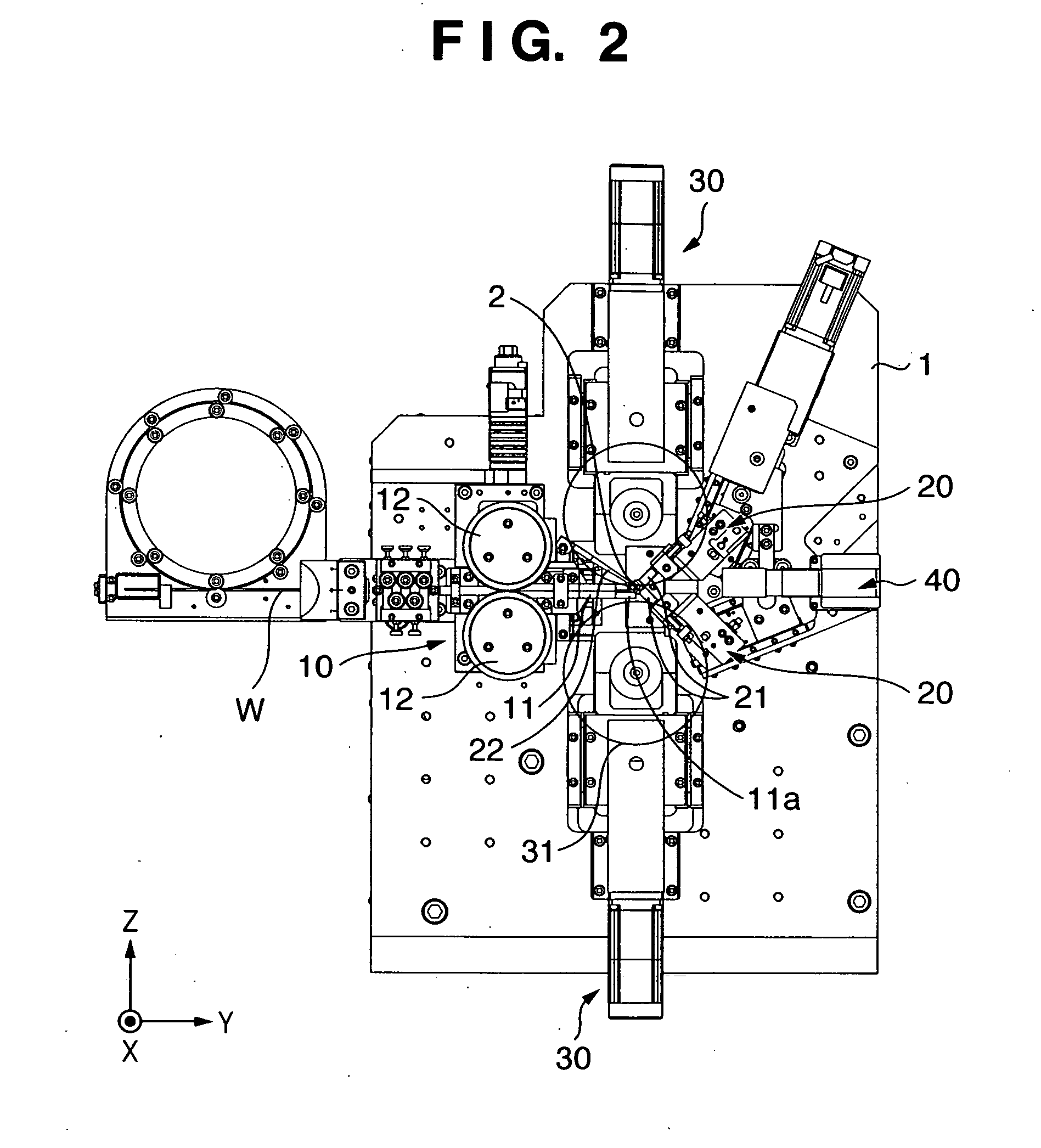
[0113]FIG. 11 is a perspective view showing an external appearance of a helical part manufacturing apparatus according to the second embodiment of the present invention. In the drawing, the discoid grindstone of the grindstone tool unit can be seen through. FIG. 12 is a front elevation of FIG. 11. Note that the chuck is omitted in FIGS. 11 and 12.

[0114]The configuration shown in FIGS. 11 and 12 has a laser unit 50 in place of the grindstone tool unit 30 described in the first embodiment. Note that the measurement unit 40 is omitted in the drawing. For the structure in common with that of FIG. 1, identical reference numerals are assigned and descriptions thereof are omitted. The position of the laser unit 50 may be switched with...

third embodiment

[0124]In the above-described first and second embodiments, the discoid grindstones 31 of the grindstone tool units 30 are arranged vertically (in the Z direction) so that the moving direction of the discoid grindstones 31 is orthogonal to the wire feeding direction (Y direction). However, in the third embodiment, a discoid grindstone 81 of the grindstone tool unit 80 is arranged in a manner that the discoid grindstone 81 moves along the wire feeding direction and is positioned opposite to the wire feeding direction. More specifically, the discoid grindstone 81 is arranged at the position where the pointing tool 21 is arranged in the first embodiment, i.e., a position along the wire feeding direction and opposite to the guide 11.

[0125]FIG. 15 is a perspective view showing an external appearance of a helical part manufacturing apparatus according to the third embodiment of the present invention. In the drawing, the discoid grindstone of the grindstone tool unit can be seen through. FI...


PUM

PropertyMeasurementUnit
Lengthaaaaaaaaaa
Thicknessaaaaaaaaaa
Diameteraaaaaaaaaa

Abstract

This invention provides an apparatus for manufacturing a helical part by feeding a wire W toward a pointing tool 21 and pushing the wire W against the pointing tool 21 to forcibly wind the wire. The apparatus comprises: a feed roller 12 for feeding the wire W toward the pointing tool 21; a wire feeding motor 111 for rotatably driving the feed roller; a grindstone tool unit 30, which holds a discoid grindstone 31 rotatable and movable, for cutting the wire W by the rotating discoid-grindstone 31; and a CPU 100 for controlling the wire feeding motor 111 and grindstone tool unit 30 to move the discoid grindstone 31 on a plane which is substantially perpendicular to a coil growing direction of the helical part and to cut the wire W in a direction which is substantially perpendicular to the coil growing direction.

Description

CROSS-REFERENCE TO RELATED APPLICATION[0001]This application is entitled to the benefits of Japanese Patent Application Nos. 2007-149573, filed Jun. 5, 2007 and 2008-128774, filed May 15, 2008.BACKGROUND OF THE INVENTION[0002]1. Field of the Invention[0003]The present invention relates to a manufacturing technique of helical parts, typically exemplified by coil springs or the like.[0004]2. Description of the Related Art[0005]Conventionally, a spring has been manufactured by helically winding a wire by a spring manufacturing apparatus which serves as a helical part manufacturing apparatus, and then both ends of the spring are processed into flat surfaces with the use of a grinding machine which is provided differently from the spring manufacturing apparatus. The necessity of the differently provided grinding machine has been causing problems in terms of costs and machine installing locations. Also, the grinding process necessary in addition to the spring manufacturing process has bee...

Claims


Application Information

Patent Timeline
IPC IPC(8): B21F3/02B21F3/10
CPCB21F3/02
Inventor ITAYA, ICHIRO
Owner ITAYA SEISAKUSHO
Why Eureka
Try Eureka