Tub for humidifier

a technology for humidifiers and tubs, which is applied in the direction of couplings, combustion types, lighting and heating apparatuses, etc., can solve the problems of reducing the usable capacity of water containers, reducing the efficiency of humidification, so as to achieve the effect of increasing the usable water capacity

Active Publication Date: 2008-12-11
RESMED LTD
View PDF11 Cites 164 Cited by
  • Summary
  • Abstract
  • Description
  • Claims
  • Application Information

AI Technical Summary

Benefits of technology

[0008]Another aspect of the invention relates to a humidifier tub that provides increased usable water capacity for use with a CPAP device.

Problems solved by technology

However, in seeking to reduce the size of the CPAP machines there has been a trade-off between reduced size on the one hand and reduced performance on the other.
Reducing the size of CPAP machines, including humidifiers, has led to a decrease in the size of water containers making it more difficult to provide humidification of the air supply during the entirety of the patient's sleep cycle.
This creates problems in maintaining a sufficient moisture pickup by the airflow passing through the tub and requires that the flow generator motor run faster, which produces more noise.
The integration of humidifiers with flow generators also makes it more difficult to clean the water container of the humidifier.

Method used


Image

  • Tub for humidifier
  • Tub for humidifier
  • Tub for humidifier

Examples


first embodiment

2.0 Tub First Embodiment

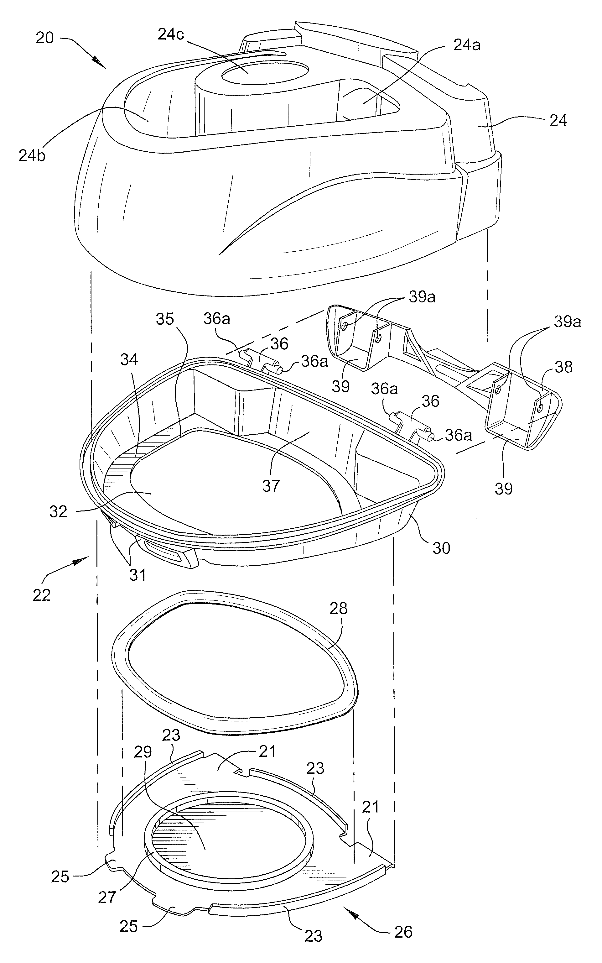
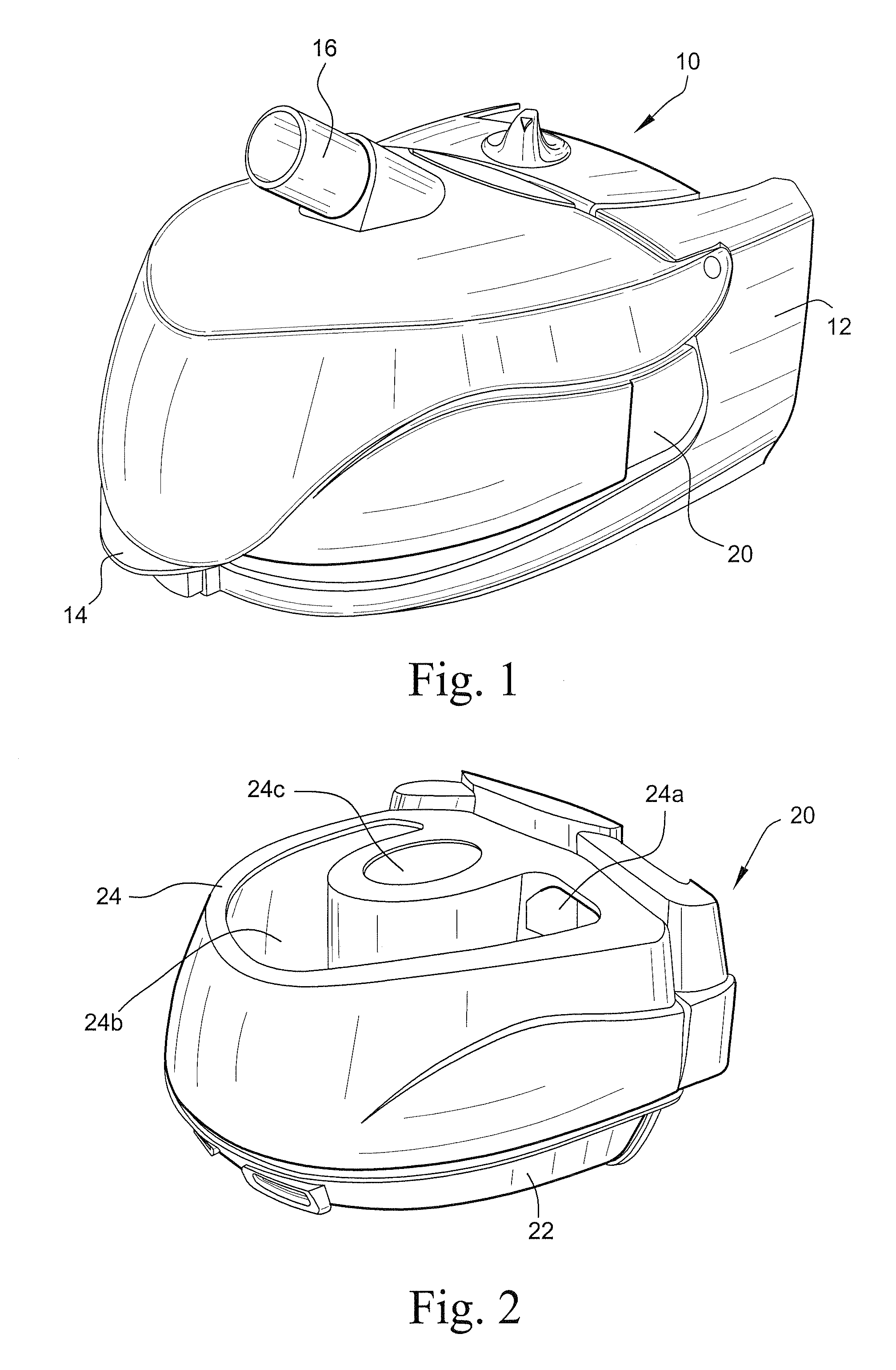
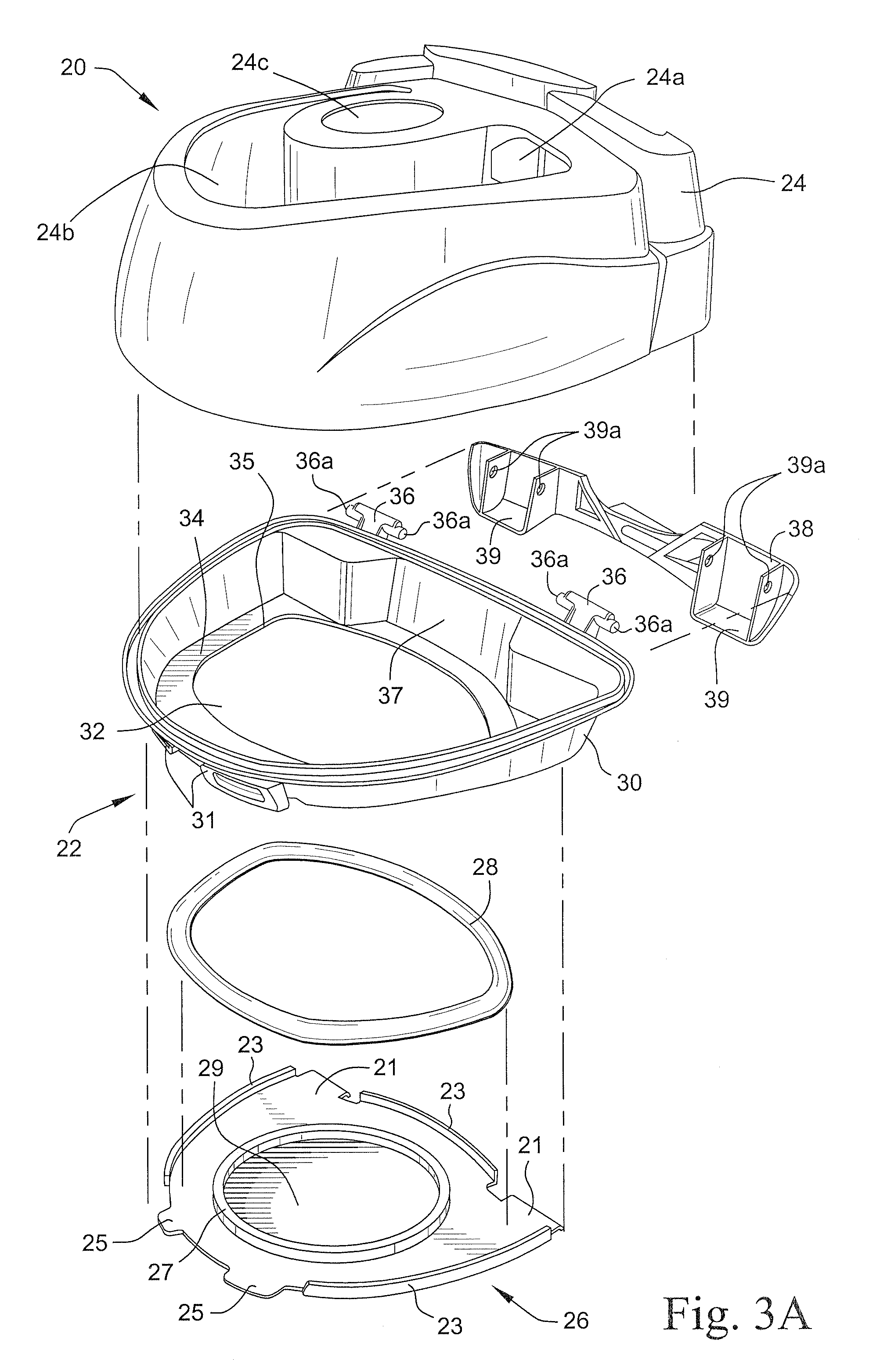
[0051]As shown in FIG. 2, the water container 20 includes a tub 22 and a tub lid 24. The tub lid 24 includes an air inlet aperture 24a that communicates with an air outlet aperture of the flow generator when the humidifier 10 is connected to the flow generator. The tub lid 24 also includes a U-shaped air passage 24b and a humidified air outlet 24c. The humidified air outlet 24c communicates with the air outlet pipe 16 when the hinged lid 14 is in the position shown in FIG. 1 to deliver humidified air to the delivery hose.

[0052]Referring to FIG. 3A, the tub 22 includes a base plate 26 and a tub base 30. The base plate 26 may be formed by stamping, for example, a stainless steel plate. A stamped ring 27 may be formed on the base plate 26 to provide structural rigidity to the base plate 26 so as to provide a flat surface 29. The base plate 26 is also formed with alignment tabs 25 and latch tabs 21.

[0053]A face seal 28 is provided between the base plate 26 and th...

second embodiment

2.1 Tub Second Embodiment

[0061]Referring to FIGS. 5 and 6, according to another embodiment of the present invention, the tub base 30a may include a plurality of locking tabs 40a-40d. The base plate 26a is inserted over the opening 32a in the tub base 30a as shown by the arrows in FIG. 5. It should also be appreciated that the base plate 26a may be inserted over the opening in a direction perpendicular to the direction shown by the arrows. The locking tabs 40a-40d are resilient and are received in locking slots 42a-42d provided in the base plate 26a in a snap-in manner. A groove 44 surrounds the periphery of the opening 32a in the tub base for receipt of a seal 46, such as an O-ring. The tub base 30a may also include fastener fittings 41 for receipt of fasteners 48. It should be appreciated that the fasteners 48 may be any releasable fastener.

third embodiment

2.2 Tub Third Embodiment

[0062]Referring to FIG. 7, the base plate 26b may be releasably secured to the tub base30b by tabs 33 formed on the tub base 30b and snap rings 50. The base plate 26b is placed over the opening 32b in the tub base 30b in contact with the seal 46b. The snap rings 50 are then placed over the base plate 26b and in engagement with the tabs 33 to secure the base plate 26b between the snap rings 50 and the seal 46b. The tabs 33 are resiliently deformed by insertion of the snap rings 50 so that the snap rings 50 are secured in the position shown in FIG. 7.


PUM


Abstract

A humidifier includes a tub. The tub includes a base plate; a tub base; a seal between the base plate and the tub base; and a latch mechanism that connects the base plate to the tub base so that the base plate is engaged with the seal. The latch mechanism may include an overcenter latch pivotably attached to the tub base and latch tabs formed on the base plate, the overcenter latch engaging the latch tabs in the connected position to connect the base plate to the tub base. The latch mechanism may alternatively include resilient tabs on the tub base, the resilient tabs elastically biasing the base plate toward the tub base upon connection of the base plate to the tub base. The resilient tabs may include tamper evident projections that indicate that the base plate has been disconnected from the tub base. The base plate may be stainless steel and be formed by stamping. The base plate may include a stamped ring. The humidifier further includes a tub lid configured to cover the tub to form a water container. A cradle receives the water container. A hinged lid on the cradle is pivotable between an open position permitting insertion of the water container into the cradle and a closed position covering the inserted water container. A heating element contacts the base plate when the water container is inserted into the cradle. The humidifier is connectable to a flow generator of a CPAP device.

Description

CROSS REFERENCE TO RELATED APPLICATION[0001]This application claims priority to U.S. Applications 60 / 942,567, filed Jun. 7, 2007, and 61 / 039,514, filed Mar. 26, 2008, the entire contents of both being incorporated herein by reference.FIELD OF THE INVENTION[0002]The present invention relates to a tub for a humidifier. The present invention also relates to a humidifier for a breathable gas supply apparatus, and particularly but not exclusively, to such apparatus for use in Continuous Positive Airway Pressure (CPAP) treatment of conditions such as Obstructive Sleep Apnea (OSA) and other respiratory disorders and diseases such as emphysema. Although the present invention is described herein in its application to CPAP treatment apparatus, it should be appreciated that the features of the present invention will have application to other fields of application, such as a mechanical ventilation and assisted respiration.BACKGROUND OF THE INVENTION[0003]CPAP treatment of OSA, a form of Noninva...

Claims


Application Information

Patent Timeline
Patent Type & Authority Applications(United States)
IPC IPC(8): A62B9/00
CPCA61M16/1075A61M16/16A61M16/0057Y10T403/59Y10T403/608Y10T403/60A61M16/109
Inventor SNOW, JOHN MICHAELCORK, SIMON ROBERTZEKIC, JOHNHUNTER, BENJAMIN JOHN
Owner RESMED LTD
Why Eureka
Try Eureka