Wet type friction plate

a friction plate and wet type technology, applied in the direction of fluid actuated clutches, clutches, non-mechanical actuated clutches, etc., can solve the problems of increased plate quality, limited or severely restricted groove size, and reduced drag during idle rotation, so as to reduce the drag torque between the friction surfaces, reduce the excessive supply of oil, and reduce the effect of drag

Inactive Publication Date: 2008-12-11
NSK WARNER
View PDF7 Cites 15 Cited by
  • Summary
  • Abstract
  • Description
  • Claims
  • Application Information

AI Technical Summary

Benefits of technology

[0015]According to the present invention, the following effects can be obtained.
[0016]Since the friction surface of the friction material is provided with the plurality of first recessed portions each including the opening portion opened to the inner diameter side and the end portion closed between the inner and outer diameter sides of the friction material and the plurality of second recessed portions each including the opening portion opened to the outer diameter side and the end portion closed between the inner and outer diameter sides of the friction material, drag during the idle rotation can be reduced in all of rotating areas from low speed rotation to high speed rotation.
[0017]The plurality of first recessed portions each including the opening portion opened to the inner diameter side and the end portion closed between the inner and outer diameter sides of the friction material serve to generate oil flow for returning the oil in the first recessed portions to the inner diameter side by actions of wall surfaces of the recessed portions and interaction of oil viscosity caused by a rotational difference between the friction plate and the separator plate, during the low speed idle rotation. Thus, positive pressure is generated in the first recessed portion which generates a force for separating the friction plate and the separator plate from each other, thereby preventing the seizure between the friction plate and the separator plate and reducing the excessive supplying of oil to the friction material and reducing the drag torque between the friction surfaces.
[0018]Further, the plurality of second recessed portions each including the opening portion opened to the outer diameter side and the end portion closed between the inner and outer diameter sides of the friction material serve to generate a force for discharging the oil in the recessed portions outside by actions of wall surfaces of the recessed portions and interaction of oil viscosity caused by a rotational difference between the friction plate and the separator plate, thereby positively discharging the oil supplied to the friction surface to the outer diameter side through the opening portions. In this way, since the oil can be discharged from the friction surface quickly, the drag during the idle rotation can be reduced.
[0019]Further, in the high speed idle rotation, the amount of oil discharged from the second recessed portions having the opening portions opened to the outer diameter side is more increased to generate negative pressure in the recessed portions, so that air is sucked into the recessed portions from the outer diameter side, and the sucked air is supplied to the friction surface, where the air is mixed with the oil on the friction surface, thereby reducing the idle rotation drag more greatly.

Problems solved by technology

Although the oil from the oil groove extending through from the inner periphery to the outer periphery in the radial direction is used to supply the oil to the friction surface and to discharge the oil, the flow of the oil from the oil groove to the friction surface is greatly influenced by a configuration of the oil groove and the like, with the result that the oil flow affects an influence upon the idle rotation torque and the friction property during the engagement, thereby causing dispersion in plate quality.
Regarding the friction materials of these friction plates, although the oil from the oil groove extending through from the inner periphery to the outer periphery in the radial direction is used to supply the oil to the friction surface and to discharge the oil, the flow of the oil from the oil groove to the friction surface is greatly influenced by the configuration of the oil groove and dull both side corners of the groove, with the result that the oil flow affects an influence upon the idle rotation torque and the friction property during the engagement, thereby causing dispersion in plate quality.
To this end, the increase in the number of grooves to be formed in the friction plate and the size of the groove have been limited or restricted severely.

Method used


Image

  • Wet type friction plate
  • Wet type friction plate
  • Wet type friction plate

Examples


first embodiment

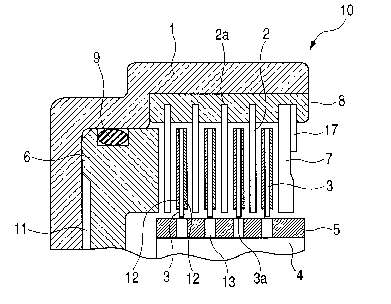
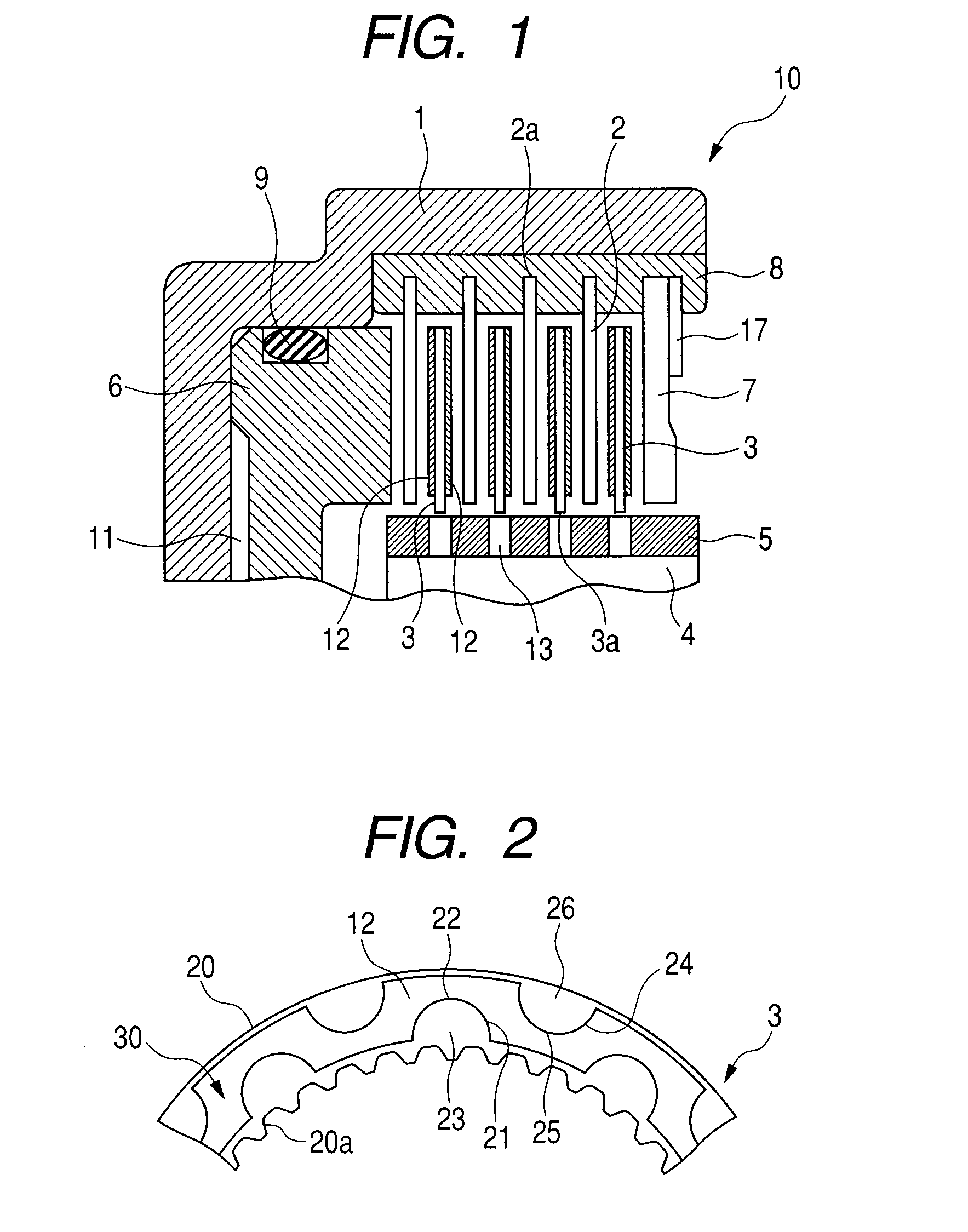
[0035]FIG. 2 is a front view of a wet type friction plate according to a first embodiment of the present invention. The wet type friction plate 3 has a friction surface 30 formed by sticking a substantially annular friction material 12 to a substantially annular core plate 20 by an adhesive and the like. The core plate 20 is provided at its inner periphery with splines 20a adapted to be engaged by the spline portion 5 of the hub 4.

[0036]As shown, a plurality of first recessed portions 21 and a plurality of second recessed portions 24, which are equidistantly spaced apart from each other along a circumferential direction and are disposed alternately, are formed in the friction material 12. The plurality of first recessed portions 21 each having an opening portion 23 opened to an inner diameter side and an end portion 22 closed between inner and outer diameter sides of the friction material 12 and the plurality of second recessed portions 24 each having an opening portion 26 opened to...

second embodiment

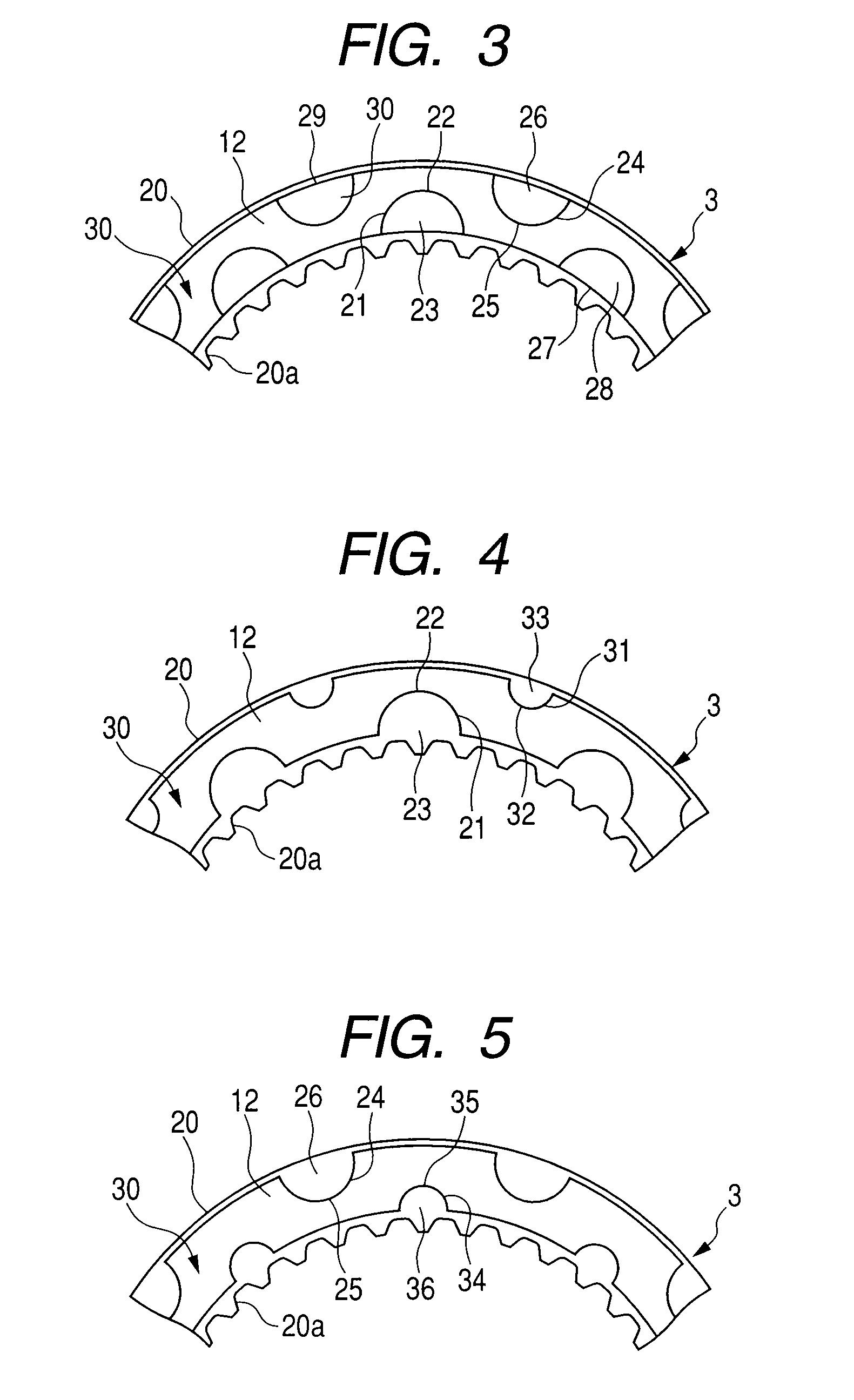
[0040]FIG. 3 is a front view of a wet type friction plate according to a second embodiment of the present invention. Although a fundamental construction of the third embodiment is the same as that of the first embodiment, a method for forming the first recessed portions 21 and the second recessed portions 24 differs from that of the first embodiment. Accordingly, only the difference will be described.

[0041]In the first embodiment, although the friction material 12 in which the first recessed portions 21 and the second recessed portions 24 were previously formed by the punching are secured to the core plate 20, in the second embodiment, the first recessed portions 21 and the second recessed portions 24 are formed by press-forming such recessed portions in the annular friction material 12 secured to the core plate 20.

[0042]As shown in FIG. 3, an inner peripheral edge 27 of the friction material 12 remains at the opening portion 23 of the first recessed portion 23 and a bottom surface ...

third embodiment

[0043]FIG. 4 is a front view of a wet type friction plate according to a third embodiment of the present invention. The third embodiment is an alteration of the first embodiment, in which sizes of recessed portions differ from each other at inner and outer diameter sides of the friction material 12.

[0044]A first recessed portion 21 disposed at the inner diameter side is the same as that of the first embodiment. In the third embodiment, as shown in FIG. 4, second recessed portions 31 disposed at the outer diameter side differ from those of the first embodiment. Each of the plurality of second recessed portions 31 has an opening portion 33 opened to the outer diameter side and an end portion 32 closed between the inner and outer diameter sides of the friction material 12.

[0045]Both of a circumferential width and a radial length of the opening portion of the second recessed portion 31 are smaller than those of the first recessed portion 21. This arrangement is effective in a case where...


PUM


Abstract

The present invention provides a wet type friction plate having a friction surface formed by securing a friction material to a substantially annular core plate in an annular fashion, in which the friction surface is provided with a plurality of first recessed portion each including an opening portion opened to an inner diameter side and an end portion closed between inner and outer diameter sides of the friction material and a plurality of second recessed portions each including an opening portion opened to the outer diameter side and an end portion closed between the inner and outer diameter sides of the friction material, and the first recessed portions and the second recessed portions are arranged alternately along a circumferential direction, wherein each of said first recessed portions and said second recessed portions has a maximum circumferential width at said opening portion.

Description

BACKGROUND OF THE INVENTION[0001]1. Field of the Invention[0002]The present invention relates to a wet type friction plate used in a speed change clutch, a lock-up clutch for a torque converter, a wet type multi-plate clutch for a starting clutch and the like utilized in a clutch or a brake and the like of an automatic transmission (AT) of a vehicle.[0003]2. Related Background Art[0004]In general, in a wet type multi-plate clutch, friction plates and separator plates are disposed alternately between a drum and a hub of a clutch or a brake so that the clutch is engaged and disengaged by applying to and releasing from a pressing force with respect to the plates by means of a clutch piston, respectively.[0005]Further, in recent years, low fuel consumption of a motor vehicle has been requested more and more, and, also in an automatic transmission, reduction in drag torque between the friction plate and the separator plate has been requested more and more in order to reduce power loss du...

Claims


Application Information

Patent Timeline
Patent Type & Authority Applications(United States)
IPC IPC(8): F16D13/64
CPCF16D13/64F16D13/648F16D2069/004F16D25/0638F16D25/123
Inventor TAKAYANAGI, KEI
Owner NSK WARNER
Why Eureka
Try Eureka