
Dynamic Ring Oscillators

a technology of dynamic rings and oscillators, applied in pulse generators, instruments, pulse techniques, etc., can solve the problems of more difficult to measure parameters, and achieve the effect of easy observation and measurement of electrical characteristics, difficult to measure parameters, and advantageously

Active Publication Date: 2008-12-11
INTELLECTUAL VENTURES HOLDING 81 LLC
View PDF50 Cites 2 Cited by
  • Summary
  • Abstract
  • Description
  • Claims
  • Application Information

AI Technical Summary

Benefits of technology

[0006]Advantageously, easily observed and measured electrical characteristics of the ring oscillator such as the oscillating frequency (e.g., the operating frequency of the oscillating ring) can reveal more difficult to measure parameters, such as the operating delay of the oscillator's dynamic circuits. Even properties deeply embedded within the microscopic and submicroscopic structures comprising the component elements of the circuit can be revealed.
[0007]For instance, subtle frequency differences between the oscillations of complimentary N type and P-type oscillating rings, which are ostensibly otherwise identical (e.g., in design and fabrication) can indicate relative P to N ratios such as the relative strengths of the component N-type field effect transistors (FETs) and P-type FETs (NFETs and PFETs, respectively). Further, this is indicated by the embodiments described herein, to levels of accuracy and precision that conventionally can be costly and / or troublesome achieve, and require high precision analog apparatus to measure.

Problems solved by technology

Advantageously, easily observed and measured electrical characteristics of the ring oscillator such as the oscillating frequency (e.g., the operating frequency of the oscillating ring) can reveal more difficult to measure parameters, such as the operating delay of the oscillator's dynamic circuits.

Method used


Image

  • Dynamic Ring Oscillators
  • Dynamic Ring Oscillators
  • Dynamic Ring Oscillators

Examples


Embodiment Construction

[0028]The present invention relates to the field of electronics. More specifically, embodiments of the present invention relate to circuits, systems and methods relating to dynamic ring oscillators. Exemplary embodiments of circuits, systems and methods relating to a dynamic ring oscillator are described below. Reference will now be made in detail to embodiments of the present invention, examples of which are illustrated in the accompanying drawings. While the present invention will be described in conjunction with the following embodiments, it will be understood that they are not intended to limit the present invention to these embodiments alone. On the contrary, the present invention is intended to cover alternatives, modifications, and equivalents which may be included within the spirit and scope of the present invention as defined by the appended claims. Furthermore, in the following detailed description of the present invention, numerous specific details are set forth in order ...


PUM


Abstract

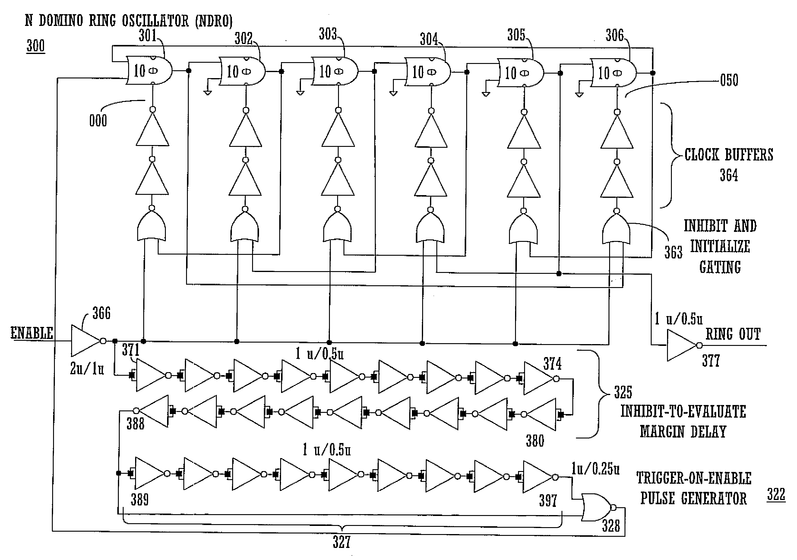
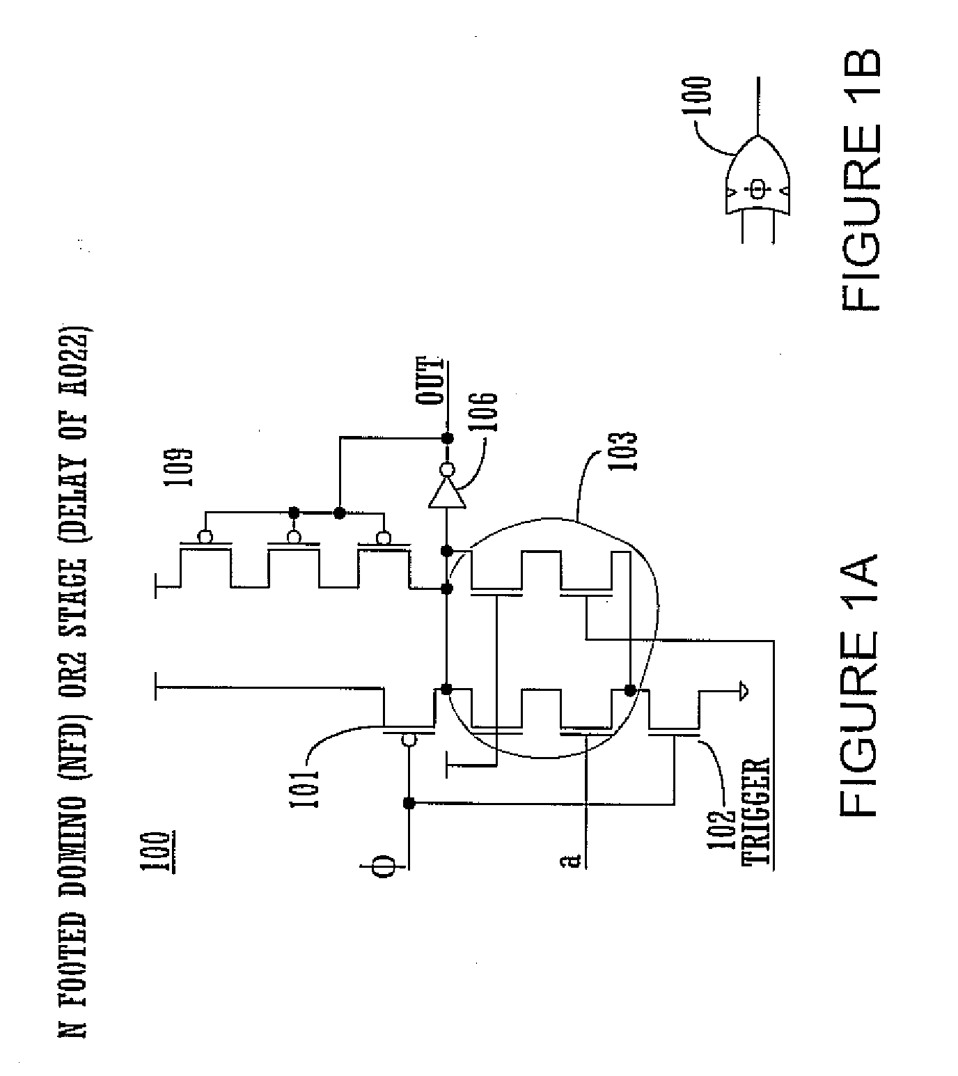
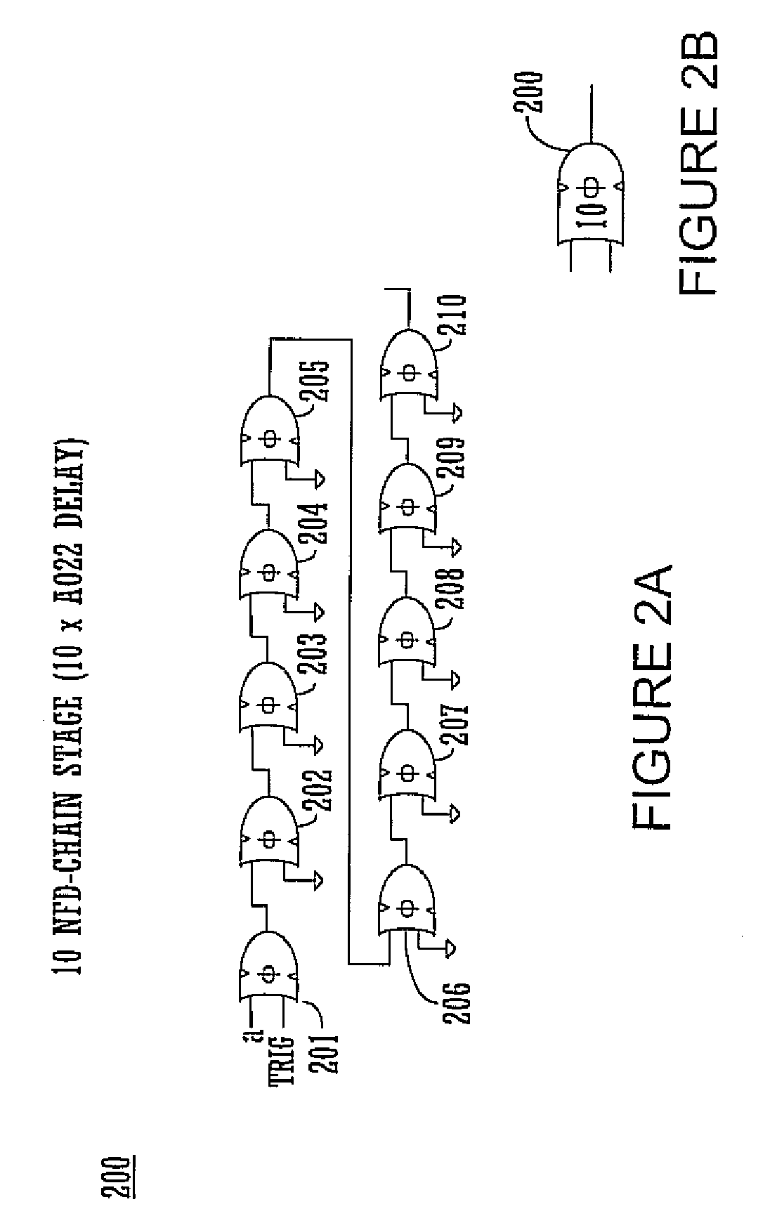
A dynamic oscillating ring circuit is described, which has multiple non-inverting domino circuits, each having a signal input, a trigger input, inputs for charge state clock and clocked cutoff and an output inverter. A number of the domino circuits are coupled in series, the output of one feeding the input of the next, to form a chain, which form stages of the ring. A number of the stages are coupled in series, the output of one feeding the input of the next, to form the ring. The first domino circuit of said chain receives a logic signal input and a single trigger input for the chain. Within the ring, the output of each stage feeds the input signal to the next stage and is fed back to clock an earlier stage to allow the ring to oscillate.

Description

CROSS-REFERENCE TO RELATED APPLICATIONS[0001]This is a continuation of U.S. patent application Ser. No. 11 / 322,595 filed Dec. 30, 2005, which is incorporated in its entirety herein by reference.BACKGROUND OF THE INVENTION[0002]Ring oscillators conventionally have an odd number of inversion stages and typically use static circuits. These properties can constrain the usefulness of conventional ring oscillators in some applications.SUMMARY OF THE INVENTION[0003]Accordingly, a ring oscillator that is unconstrained by properties inherent in conventional ring oscillators may achieve utility in the applications in which conventional ring oscillators cannot effectively function.[0004]A dynamic oscillating ring circuit is described, which has multiple non-inverting domino circuits, each having a signal input, a trigger input, inputs for charge state and cutoff clocks and an output inverter. An even number of the domino circuits are coupled in series, the output of one feeding the input of th...

Claims


Application Information

Patent Timeline
Patent Type & Authority Applications(United States)
IPC IPC(8): H03B5/24
CPCH03K3/0315
Inventor MASLEID, ROBERT P.
Owner INTELLECTUAL VENTURES HOLDING 81 LLC
Learn More