Noise Reduced Variable Displacement Vane Pump

a variable displacement, vane pump technology, applied in the direction of machines/engines, rotary/oscillating piston pump components, liquid fuel engines, etc., can solve the problems of generating undesirable noise, damage to pump components, and suffer from some disadvantages, so as to reduce or prevent the ingestion of air, reduce the noise of operation and reduce the occurrence of cavitation

Inactive Publication Date: 2008-12-11
MAGNA POWERTRIAN INC (US)
View PDF2 Cites 5 Cited by
  • Summary
  • Abstract
  • Description
  • Claims
  • Application Information

AI Technical Summary

Benefits of technology

[0007]The present invention provides a novel and useful improvement to vane pumps, both variable displacement vane pumps and fixed displacement vane pumps, by providing a supply of pressurized fluid to the region within the diameter of the pump rotor which would otherwise be a region of reduced pressure wherein air could be ingested by the pump. By reducing or preventing the ingestion of air, operating noise and damage to the pump can be reduced. Further, a portion of the supply of pressurized working fluid to this region can act to supercharge the pump, reducing the occurrence of cavitation. Also, reducing or preventing the ingestion of air allows a pump, in accordance with the present invention, to produce higher output pressures of the working fluid during start-up with cold working fluid than a conventional pump could achieve, providing various benefits including reducing engine wear when the pump is a lubricating pump in a vehicle engine.

Problems solved by technology

However, while vane pumps, and in particular VDVPs, can provide several advantages over gear pumps or other pumps, they do suffer from some disadvantages.
In particular, vane pumps can generate undesirable levels of noise when operating and / or can suffer from cavitation effects which, over time, damage components of the pumps.

Method used


Image

  • Noise Reduced Variable Displacement Vane Pump
  • Noise Reduced Variable Displacement Vane Pump
  • Noise Reduced Variable Displacement Vane Pump

Examples


Embodiment Construction

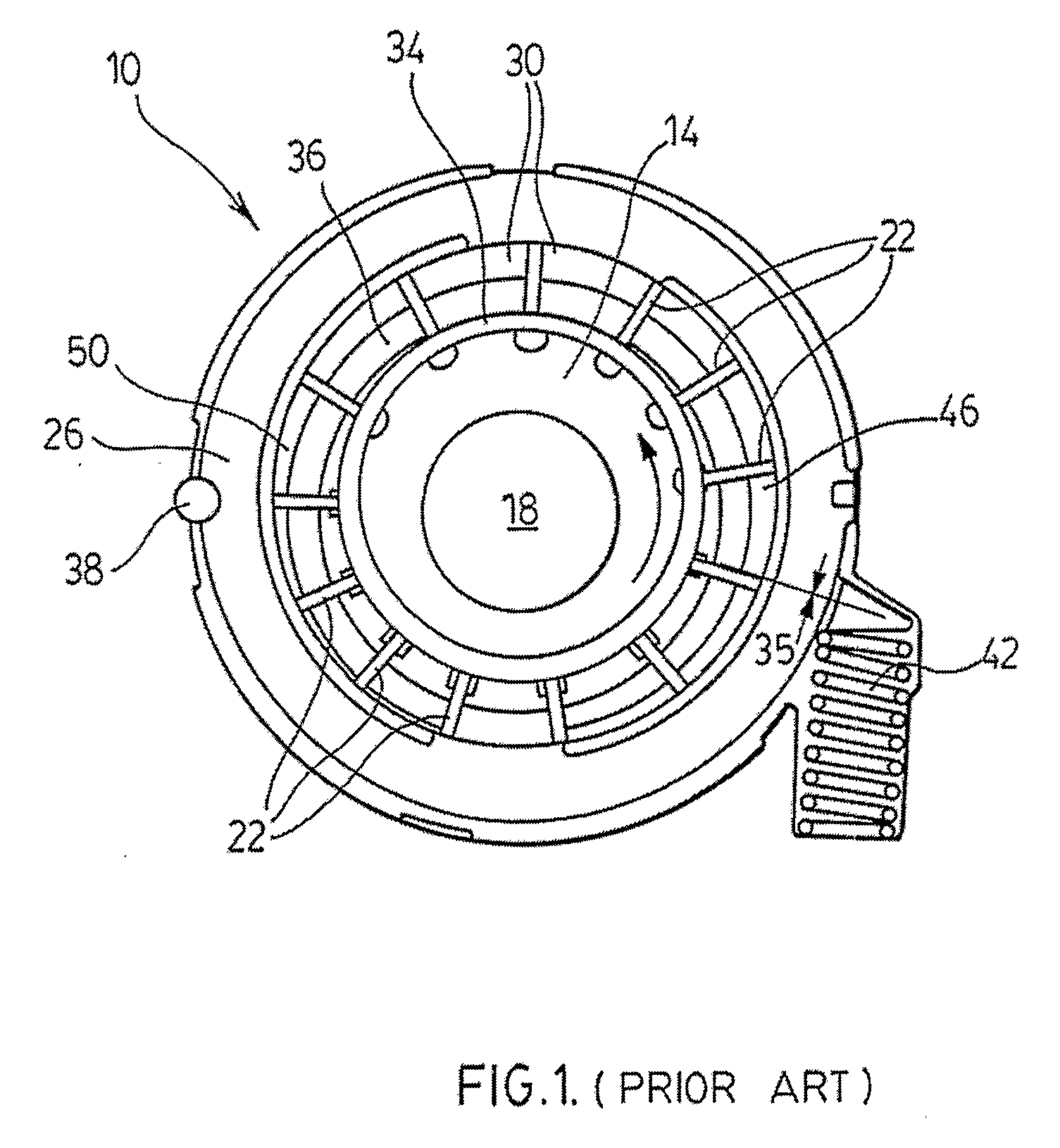
[0011]Before describing the present invention, a prior art variable displacement vane pump will be described, for clarity, with respect to FIG. 1. Prior art VDVP 10 includes a closed housing with a rotor 14 with a central bore 18 which engages and is rotated by a drive shaft (not shown). Rotor 14 includes a plurality of radially extending vanes 22 which engage the inner surface of a pump control ring 26 to form a series of pump chambers 30 about rotor 14.

[0012]Vanes 22 are radially moveable into and out of rotor 14 and, as the center of rotation of rotor 14 is located eccentrically to the center of pump control ring 26, a vane control ring 34 abuts the radially inner ends of vanes 22 to maintain the outer ends of vanes 22 in contact with the inner surface of pump control ring 26 while rotor 14 rotates in a pumping direction. A rotor sealing land 36 extends between the pump cover and the rotor to substantially radially seal rotor 14 within the closed housing to define an inner rotor ...


PUM


Abstract

A novel and useful improvement to vane pumps, both variable displacement vane pumps and fixed displacement vane pumps, provides a supply of pressurized fluid to the region within the diameter of the pump rotor which would otherwise be a region of reduced pressure wherein air could be ingested by the pump. By reducing or preventing the ingestion of air, operating noise and damage to the pump can be reduced and wear in an engine or other system supplied from the pump can be reduced. The supply of pressurized working fluid also can be used to lubricate auxiliary components and/or accessories as well. Further, a portion of the supply of pressurized working fluid to this region can act to supercharge the pump, reducing the occurrence of cavitation at higher operating speeds.

Description

FIELD OF THE INVENTION[0001]The present invention relates to vane pumps. More specifically, the present invention relates to vane pumps, and particularly variable displacement vane pumps (VDVPs), which generate less noise and / or are subject to reduced cavitation problems compared to many conventional designs.BACKGROUND OF THE INVENTION[0002]Vane pumps are well known and are used in a wide variety of applications. Vane pumps have commonly been employed in automotive power steering and automatic transmission systems. More recently, vane pumps have been employed as automotive engine lubrication pumps. In particular, VDVPs have been used as automotive engine lubrication pumps as the ability to vary the displacement of the VDVP can result in increased overall efficiency of the engine.[0003]However, while vane pumps, and in particular VDVPs, can provide several advantages over gear pumps or other pumps, they do suffer from some disadvantages. In particular, vane pumps can generate undesir...

Claims


Application Information

Patent Timeline
Patent Type & Authority Applications(United States)
IPC IPC(8): F03B11/02
CPCF04C2/3442F04C14/226F04C15/0034F01C21/0836F04C15/062F04C2220/40F04C2240/30
Inventor BHOGAL, GURVINDERSETO, DAVIDBENNETT, ANDY
Owner MAGNA POWERTRIAN INC (US)
Why Eureka
Try Eureka