Multi-Stable Actuator Based on Shape Memory Alloy and Touch-Sensitive Interface Using Same

a multi-stable actuator and shape memory technology, applied in the direction of relays, valve details, electrothermal relays, etc., can solve the problems of low heat conductivity of shape memory alloys, low heat conductivity of copper alloys, and high dissipation power, so as to increase the overall efficiency of the actuator and reduce the operating cost of the actuator

Inactive Publication Date: 2008-12-18
COMMISSARIAT A LENERGIE ATOMIQUE ET AUX ENERGIES ALTERNATIVES
View PDF7 Cites 31 Cited by
  • Summary
  • Abstract
  • Description
  • Claims
  • Application Information

AI Technical Summary

Benefits of technology

[0033]The bistable or multistable actuator according to the invention has a certain advantage over the actuators of the prior art that have been described. Indeed, with the actuator of the invention, one of the shape memory alloy-based movement means is heated, causing the mobile part to move from a first stable position to a second stable position. The mobile part can then remain in this second stable position, owing to the support means, so that it is possible to stop heating the shape memory alloy-based movement means. Then, to move the mobile part again to another stable position (the first stable position for a bistable actuator or a third stable position for a multistable actuator), one or the other of the movement means is heated. It is then possible to stop heating it once the mobile part has reached said other stable position.
[0034]It can thus be seen that it is only necessary to heat the shape memory alloy-based movement means during the transient phases in which the mobile part moves between two stable positions. Since the heating of the shape memory alloy-based movement means is stopped when the mobile part is in a stable position, immobilised by the support means, the overall efficiency of the actuator is increased. This results in a reduction in the actuator operating costs because the presence of position sensors is no longer necessary.

Problems solved by technology

The actuators described in these two documents have a disadvantage in that they do not have a device enabling the moved part(s) (ring for U.S. Pat. No. 6,242,841 and free end of the last rod for U.S. Pat. No. 6,326,707) to be immobilised in two or more stable positions.
However, shape memory alloys have low heat conductivity (compared with that of copper).
Therefore, the dissipated power is high.

Method used


Image

  • Multi-Stable Actuator Based on Shape Memory Alloy and Touch-Sensitive Interface Using Same
  • Multi-Stable Actuator Based on Shape Memory Alloy and Touch-Sensitive Interface Using Same
  • Multi-Stable Actuator Based on Shape Memory Alloy and Touch-Sensitive Interface Using Same

Examples


first embodiment

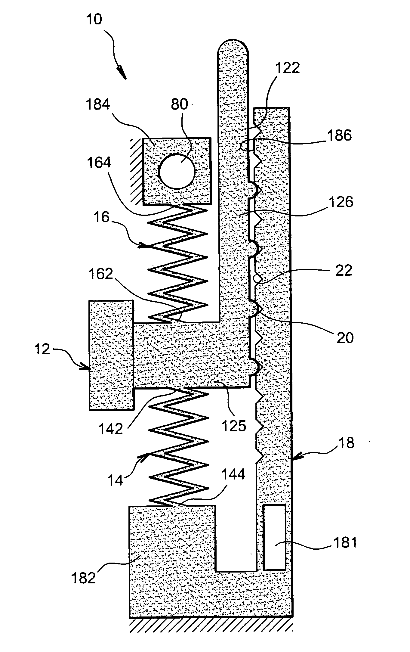
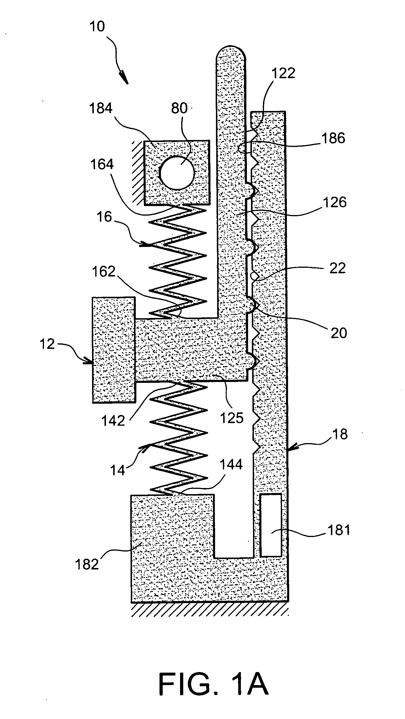
[0045]First, FIG. 1A shows a shape memory alloy-based actuator 10 according to a first alternative of the first aspect of the invention.

[0046]The actuator 10 comprises a mobile part 12 and two movement means 14, 16 for moving the mobile part 12 with respect to a reference part 18, along a rectilinear path. The reference part 18 is stationary. The two movement means are connected to the mobile part 12 on either side thereof, and act in opposition, i.e. one of the movement means 14, 16 moves the mobile part 12 in one direction, and the other of the movement means 14, 16 moves the mobile part 12 in the other direction. In the example shown, the movement means 14, 16 are in the form of two springs capable of relaxing and contracting in the direction of the movement of the mobile part 12. They are connected by one of their ends 142, 162, respectively, to the mobile part 12. They are connected by the other of their ends 144, 164, respectively, to the reference part 18 of the actuator 10, ...

second embodiment

[0056] the guide means 24 comprise a plurality of elastic beams 24. These are arranged so as to be substantially parallel to one another in a direction substantially perpendicular to the direction of movement of the mobile part 12 when they are at rest.

[0057]They are connected by one of their ends 242 to the mobile part 12, and by the other of their ends 244 to the reference part 18 of the actuator 10. The two end connections of the elastic beams 24 are embedded.

[0058]According to a first alternative of the second embodiment shown in FIG. 2, there are two elastic beams 24 and they are both placed on the same side of the mobile part 12. They connect a connection zone 124 of the mobile part to a connection zone 188 of the reference part 18, which connection zones 124, 188 are substantially parallel to one another. Thus, the assembly formed by the two elastic beams 24, the connection zone 124 of the mobile part 12 and the connection zone 188 of the reference part 18 constitutes a four-...

third embodiment

[0065] the guide means comprise a plurality of elastic beams 246, 247, 248, 249, arranged so as to be substantially parallel to one another in a direction substantially perpendicular to the direction of movement of the mobile part 12 when they are at rest.

[0066]The elastic beams are connected by one of their ends to the mobile part 12, and by the other of their ends to the reference part 18 of the actuator 10. The two end connections of the elastic beams 246, 247, 248, 249 are embedded. According to this embodiment, the reference part 18 is stationary.

[0067]The elastic beams 246, 247, 248, 249 are combined into a first pair 246, 247, arranged on a first side of the mobile part 12, and a second pair 248, 249, arranged on a second side thereof. The first pair 247, 247 connects a first connection zone 124 of the mobile part 12 to a first connection zone 188 of the reference part 18, while the second pair 248, 249 connects a second connection zone 128 of said mobile part 12 to a second ...


PUM


Abstract

The multistable actuator (10) includes:
    • a mobile part (12) intended to be moved between at least two stable positions,
    • movement means (14, 16) for moving the mobile part,
    • guide means (122, 186, 24, 246, 247, 248, 249) for guiding the movement of the mobile part (12), and
    • support means (20, 22, 28, 30, 246, 247, 248, 249) for holding the mobile part (12) in each of the stable positions that it occupies,
wherein the movement means (14, 16) are two opposing movement means made of a shape memory alloy.
Application in a tactile interface.

Description

TECHNICAL FIELD[0001]This invention relates to the technical field of alloy-based actuators.[0002]It relates to a multistable actuator, as well as an interface implementing at least one such actuator. This interface can be used to produce a tactile interface.[0003]It is noted that an actuator is a device that is capable of generating a force intended to cause the movement of a mobile part.[0004]It is noted that a multistable actuator is an actuator for which the mobile part moves between a plurality of positions each corresponding to a stable equilibrium state of the actuator.[0005]It is noted that a bistable actuator is an actuator for which the mobile part moves between two positions each corresponding to a stable equilibrium state of an actuator.[0006]It is noted that a tactile interface is a device enabling information to be detected by touch.PRIOR ART[0007]Shape memory alloys are materials well known in a number of fields.[0008]It is noted that a shape memory alloy is capable o...

Claims


Application Information

Patent Timeline
Patent Type & Authority Applications(United States)
IPC IPC(8): F03G7/06F16K31/56
CPCF03G7/065
Inventor HAFEZ, MOUSTAPHAALEXANDRE, JEAN-MARC
Owner COMMISSARIAT A LENERGIE ATOMIQUE ET AUX ENERGIES ALTERNATIVES
Why Eureka
Try Eureka