Sewing machine

a sewing machine and needle technology, applied in the field of sewing machines, can solve the problems of complicated operation, large time and labor, and achieve the effect of enhancing the operability of the sewing machine, facilitating the work of inserting, and smoothing the transition to sewing operation

Inactive Publication Date: 2008-12-18
JUKI CORP
View PDF3 Cites 9 Cited by
  • Summary
  • Abstract
  • Description
  • Claims
  • Application Information

AI Technical Summary

Benefits of technology

[0054]According to one or more aspects of the invention, the thread discharging hole of the thread path member (the thread pipe) is positioned at the retreating position in accordance with the driving operation of the sewing machine motor by the returning means (the guide member). Moreover, the air ejecting means (the air ejecting unit) is positioned at the standby position via the interlocking means (the interlocking mechanism). Consequently, it is possible to smoothly make a transition to the sewing operation even in a case where a user forgets to return the thread discha...

Problems solved by technology

Thus, there is a problem that such a operation for changing the lower looper thread T is complicated because many portions needs to be operated.
Furthermore, the...

Method used


Image

  • Sewing machine
  • Sewing machine
  • Sewing machine

Examples


first exemplary embodiment

Advantage of First Exemplary Embodiment

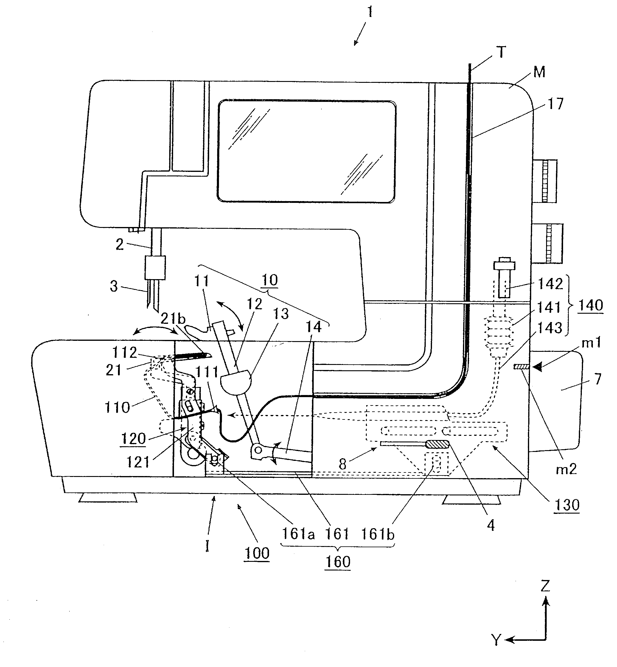
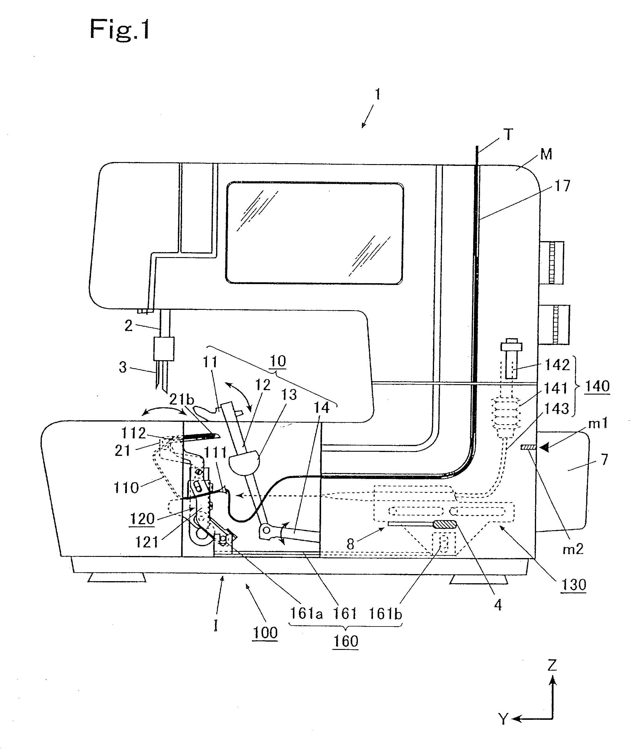
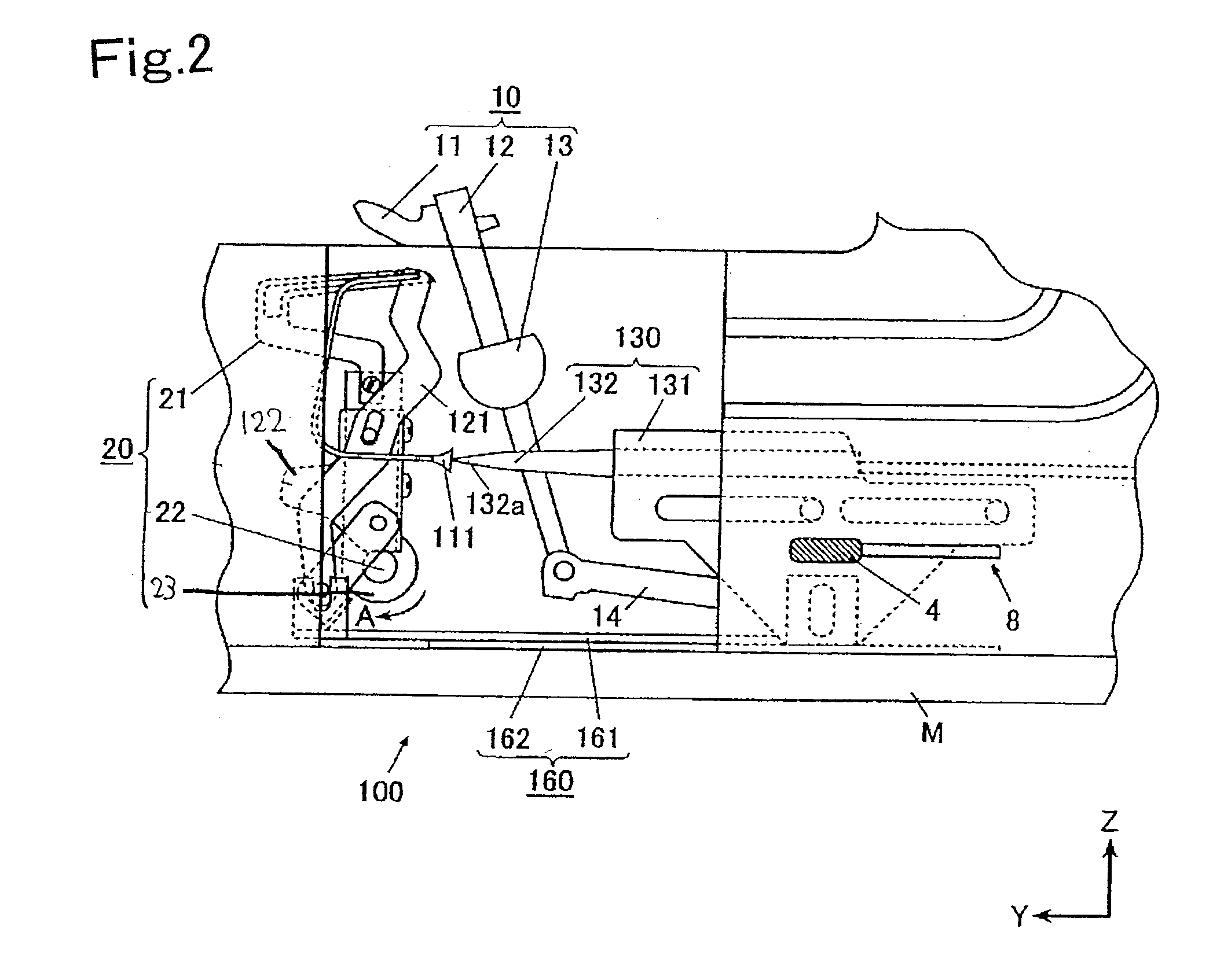
[0109]As described above, according to the sewing machine 1 of the first exemplary embodiment, when the thread discharging hole 112 of the thread pipe 110 is moved to the threading position by means of the coupling member 161, the air ejecting unit 130 is moved to the ejecting position. Similarly, when the air ejecting unit 130 is moved to the ejecting position, the thread discharging hole 112 of the thread pipe 110 is moved to the threading position. Namely, when the operation lever 4 is operated to operate one of the thread guide lever 121 or the air ejection moving means, the other can also be operated at the same time. Thus, an operation for inserting the lower looper thread T through the lower looper 21 is simplified as compared with the background art. In addition, an certain operating procedure is not required. Therefore, the threading operation can easily be carried out. Thus, it is possible to enhance operability of the sewing machine ...

second exemplary embodiment

Advantage of Second Exemplary Embodiment

[0133]According to the sewing machine 1 of the second exemplary embodiment, the thread guide lever 121 supporting the thread pipe 110 and the air ejecting unit 230 can be electrically controlled by driving the stepping motor 270. In addition, they can be controlled at the same time via the coupling member 261. In other words, the coupling member 261 and the actuator (the stepping motor 270) which drives the coupling member 261 enables a simultaneous control of the thread guide lever 121 and the air ejecting unit 230 without increasing much cost. Accordingly, the threading operation can be carried out more easily than in the background art. Thus, the operability of the sewing machine 1 can be enhanced.

Others

[0134]As shown in FIG. 10, a guide member 167 (returning means) may be may be fixed and provided in a bed portion of the sewing machine frame M. The guide member 167 positions the thread discharging hole 112 of the thread pipe 110 to the ret...


PUM


Abstract

A lower end of a thread guide lever, which is rockably attached to a lower looper and supports a thread pipe, and an air ejecting unit, which faces a thread inserting hole of the thread pipe and ejects air toward the thread inserting hole, are coupled via a coupling member so that they are interlocked with each other. The coupling member is moved such that a discharging port of an air nozzle is positioned at an ejecting position close to the thread inserting hole when a thread discharging hole is positioned at a threading position which is coincident with a thread hole of a lower looper, and such that the air nozzle is moved to a standby position when the thread discharging hole is moved to a retreating position.

Description

[0001]The present invention claims priority from Japanese Patent Application No. 2006-218233 filed on Aug. 10, 2006, the entire content of which is incorporated herein by reference.TECHNICAL FIELD[0002]The present invention relates to a sewing machine having a threading device for inserting a thread through a looper.BACKGROUND ART[0003]Some sewing machines, such as an over-edge overlock sewing machine and a double chainstitch sewing machine, has a threading device for inserting a thread through a looper by utilizing pressurized air (see, e.g., JP 2005-318932 A). As shown in FIGS. 11 to 13, such a threading device includes a lower looper driving mechanism 500 having a lower looper 510. The lower looper 510 has an extended portion 510a which is inserted into a loop of a needle thread by moving the extended portion 510a back and forth in synchronization with a vertical motion of a needle. The threading device further includes a thread pipe 520, a thread guide lever 530 which moves the ...

Claims


Application Information

Patent Timeline
IPC IPC(8): D05B1/00D05B53/00
CPCD05B1/12D05B57/08D05B63/00D05B87/02
Inventor SADASUE, KAZUYA
Owner JUKI CORP
Why Eureka
Try Eureka