Sifter

Active Publication Date: 2008-12-18
TSUKASA
View PDF12 Cites 8 Cited by
  • Summary
  • Abstract
  • Description
  • Claims
  • Application Information

AI Technical Summary

Benefits of technology

[0009]In the sifter according to this embodiment, the drum attached to the rotating shaft narrows the space of the sieving chamber to reduce the pressure loss and decrease the amount of gas (air) used for sieving. The narrowed space of the sieving chamber increases an effective area of a screen of the sieve and extends the life of the sieve. The powder is not localized in part (typically the center part) of the screen but is homogeneously dispersed to ensure stable sieving operation. This arrangement prevents the powder from being accumulated on the outer surface of the screen and reduces retention of the powder to shorten its floating time, thus enhancing the sieving yield and increasing the amount of sieved powder per unit time. In food industries, the sifter of this structure is effectively applied to reduce powder retention space inside the screen and thereby lower the potential for separation of powders in a powder mixture of various grain sizes.
[0010]In one class of this embodiment, the rotating blades protrude in a radial direction from the drum terminating close to an inner circumferential face of the sieve and extend in a direction parallel to or inclined with respect to the axial direction of the rotating shaft, and the rotating blades a

Problems solved by technology

The sieving chamber has too large of a space to sufficiently scoop up the powder by means of the rotating blades.
The powder is localized in the partial area of the angular range N. This undesirably accelerates deterioration of the screen and shortens the lifetime of the sieve, while limiting the sievin

Method used


Image

  • Sifter
  • Sifter
  • Sifter

Examples


Example

Example 1

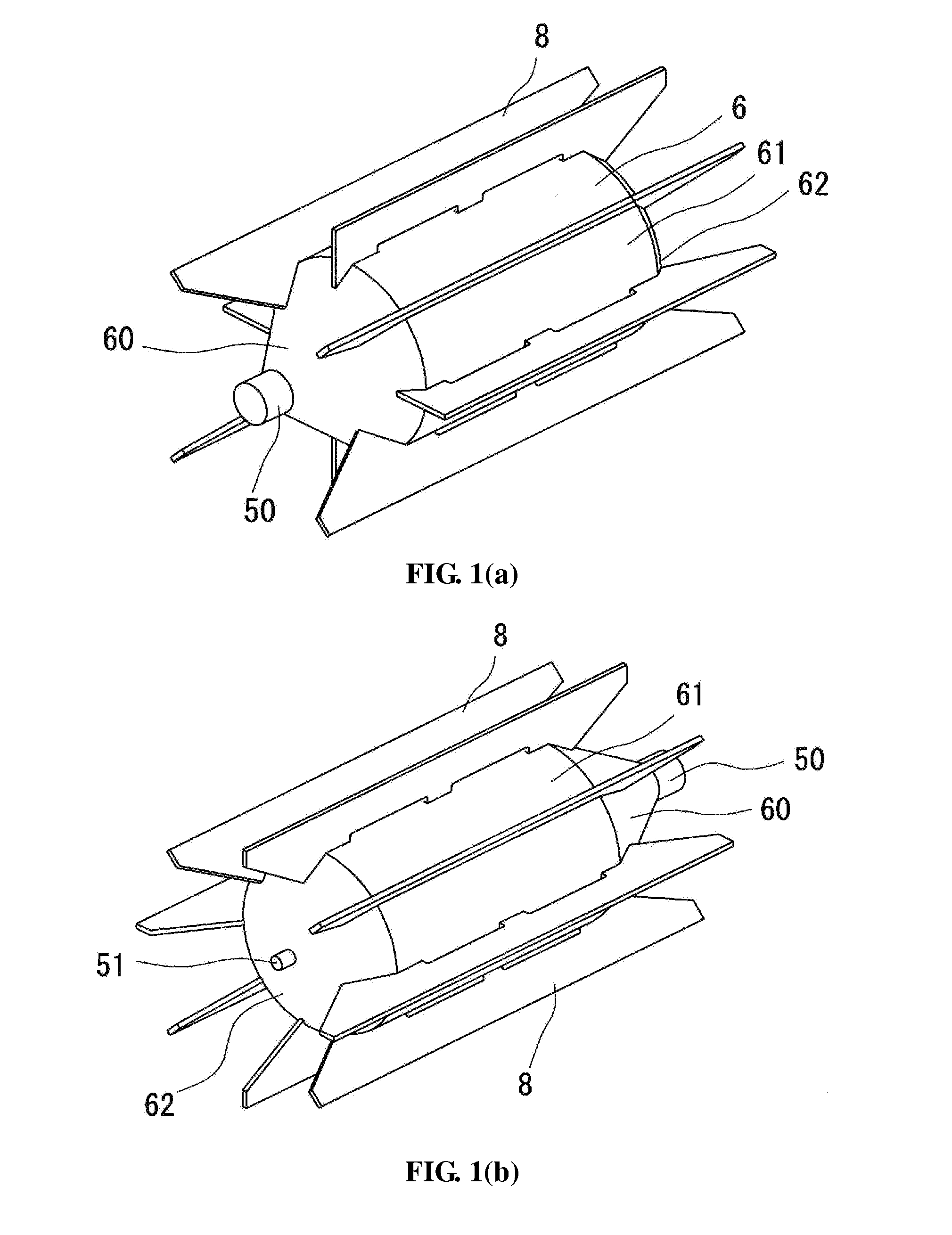
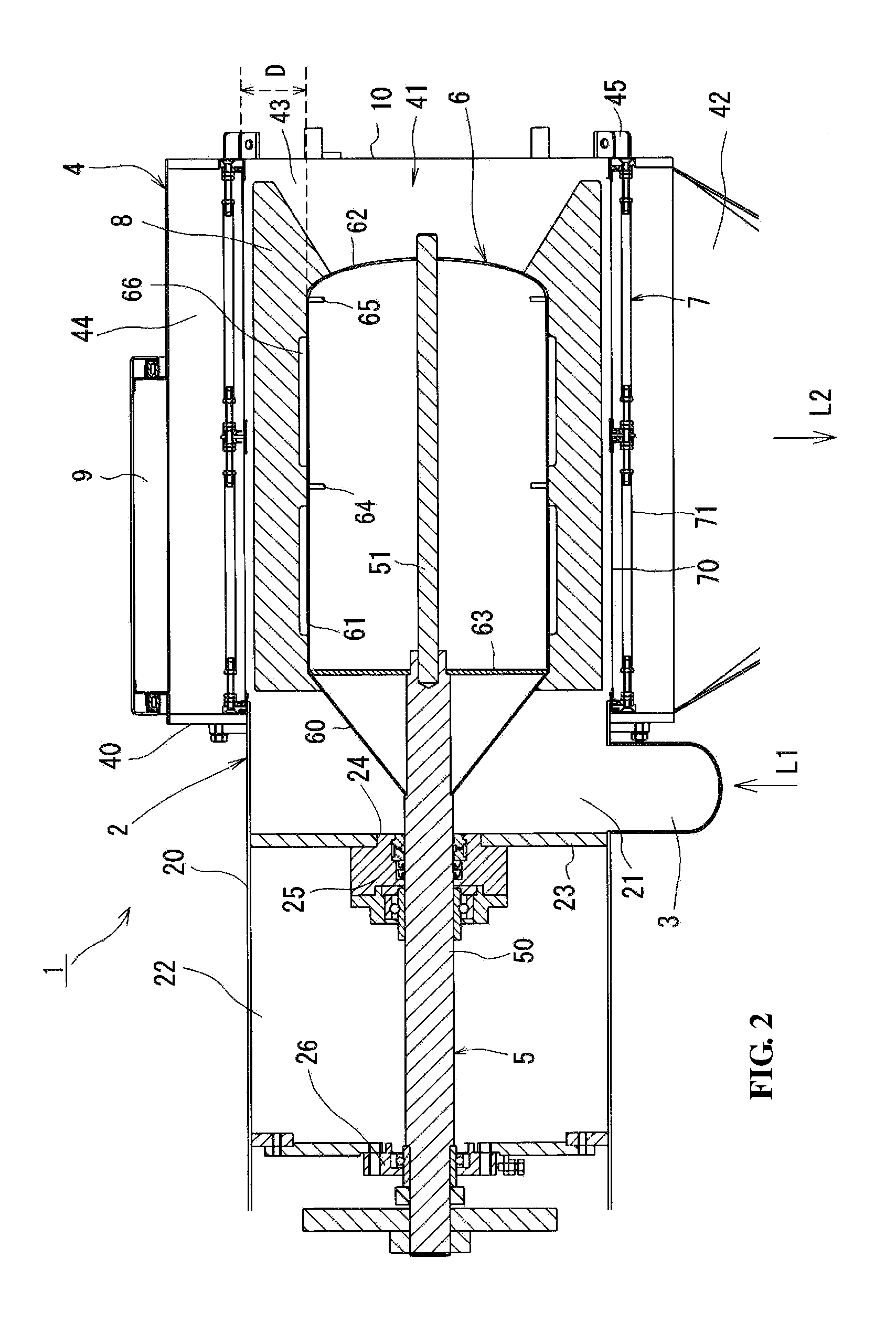
[0038]With reference to FIGS. 1-3, a pneumatic in-line sifter 1 with a mount (not shown) having support legs (not shown) comprises a receiver 2 designed to receive an air-powder mixture (i.e., pneumatically-conveyed powder); an inlet 3 connected to the receiver 2 and configured to introduce the powder supplied from an upstream line L1 via an upstream blower and an upstream rotary valve (not shown) to the receiver 2; a sieve assembly 4 coupled and communicating with the receiver 2 in a lateral direction; a rotating shaft 5 arranged in a horizontal direction to pass through the inside of the receiver 2 and the sieve assembly 4; a drum 6 attached to the rotating shaft 5, formed across the area of the receiver 2 and the sieve assembly 4 to have a larger diameter than that of the rotating shaft 5, and arranged in an axial direction of the rotating shaft 5 to be coaxial with a cylindrical sieve 7; and the cylindrical sieve 7 provided inside the sieve assembly 4, arranged around t...

Example

Example 2

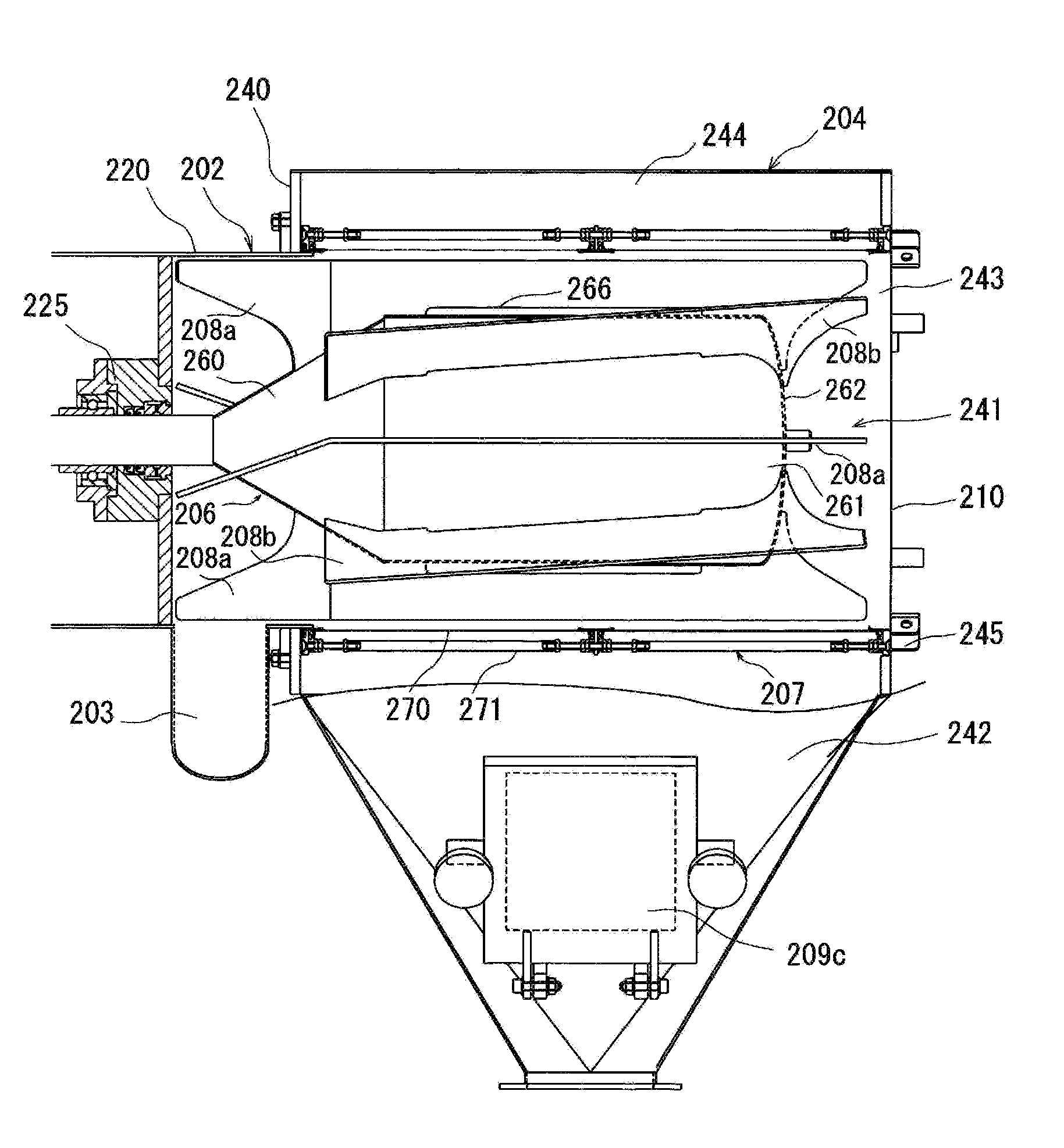
[0066]As shown in FIGS. 6 to 9, a sifter 201 has a similar structure to that of the in-line sifter 1 in Example 1 except that beaters 208 have curved edges and that parts of the beaters 208 are inclined in an axial direction toward the drum 206, as further explained below. Like constituents are expressed by corresponding numerals after adding 200 with respect to those in example 1. As shown in FIG. 8, each of the beaters 208 has one edge curved in a rotating direction of the drum 206 and inclined in the axial direction to the drum 206 to scrape out the air-powder mixture supplied from a powder inlet 203 along the circumferential direction of the drum 206. The edges of all the beaters 208 are curved in the structure of this example, although only part of the beaters may have a curved edge. The beaters 208 include four beaters 208a arranged in parallel to the axial direction and four beaters 208b inclined to the axial direction. The beaters 208a have curved concave front edge...

Example

Example 3

[0067]With reference to FIGS. 11 to 13, a sifter 301 has a similar structure to that of the sifter 201 described in example 2, except that some beaters 308 have linear edges and some beaters 308 have reinforced curved edges as explained below. Like constituents are expressed by corresponding numerals after adding 300 with respect to those in example 1. The beaters 308 include four beaters 308a arranged in parallel to an axial direction and four beaters 308b inclined to the axial direction. The beaters 308a and the beaters 308b are alternately arranged along the outer circumference of a drum 306. Among the four beaters 308a, one pair of the beaters 308a opposed to each other have linear front edges, while the other pair of the beaters 308a opposed to each other have curved front edges. The curved front edges of the beaters 308a are reinforced by triangular ribs 308c.


PUM


Abstract

A sifter comprising: a receiver having a supply chamber; a sieve assembly having a sieving chamber coupled to the supply chamber; a rotator having a rotating shaft laterally arranged to pass through the supply chamber and the sieving chamber; a drum having a circular cross-section and having a larger diameter than the diameter of the rotating shaft, the drum being extended in at least space of the sieving chamber and arranged coaxially with the sieve; a cylindrical sieve located inside the sieving chamber and arranged coaxially with the rotating shaft; a stirring rotor located in an inner area of the sieving chamber inside the sieve comprising a rotating blade attached to the rotating shaft; an extraction member; and an outlet for discharging powder passing through the sieve from the inner area to the outer area.

Description

CROSS-REFERENCE TO RELATED APPLICATIONS[0001]This application is a continuation of International Patent Application No. PCT / JP2007 / 000506, with an international filing date of May 10, 2007, designating the United States, now pending, which is based on Japanese Patent Application No. 2006-131904, filed May 10, 2006. The contents of these specifications are incorporated herein by reference.BACKGROUND OF THE INVENTION[0002]1. Field of the Invention[0003]This invention relates to a sifter for sifting powder, e.g., a food article, a chemical, or a drug in a powder form.[0004]2. Brief Description of Related Arts[0005]In conventional chute sifters, powder commonly falls through a chute into a sieving chamber and is stirred by rotation of rotating blades attached to and arranged coaxially with a rotating shaft, which is located at the center of the sieving chamber and is rotated by means of a motor. Such conventional chute sifters are described, e.g., in Japanese Laid-Open Patent Nos. S63-6...

Claims


Application Information

Patent Timeline
IPC IPC(8): B07B1/26
CPCB07B1/20B07B7/06B07B1/46
Inventor KATO, FUMIO
Owner TSUKASA
Why Eureka
Try Eureka