Linear Transverse Flux Machine

a transverse flux machine and transverse flux technology, applied in the direction of dynamo-electric machines, electrical apparatus, magnetic circuits, etc., can solve the problems of thicker air gaps, difficult to form and assemble an e-shaped core between the two windings, and general difficulty in manufacturing transverse flux machines, etc., to achieve high torque density and simple design

Inactive Publication Date: 2008-12-18
ABB RES LTD
View PDF21 Cites 12 Cited by
  • Summary
  • Abstract
  • Description
  • Claims
  • Application Information

AI Technical Summary

Benefits of technology

[0014]A primary object of the present invention is to provide a transverse flux linear machine that offers a high torque density and at the same time provides a simple design. Yet another object is to provide a transverse flux linear machine comprising a standard lamination structure.

Problems solved by technology

However, transverse flux machines are generally considered as difficult to manufacture and because of their complicated structure too expensive.
This design leads to thicker air gaps due to deformations in the construction of the movable part.
In production, however, there will be difficulty in forming and assembling an E-shaped core between the two windings.
Also this machine has four air gaps and the risk of even thicker air gaps is obvious.
One significant problem in single sided TFPM machines is the magnetic flux leakage between the stationary core and the core forming the return path of the magnetic flux.
Although possible the cores cannot be placed too narrow in the direction of the movement because of flux leakage between the core pieces.
Even though the known transverse flux machines may be designed to be more efficient they still exhibit a plurality of parts that must be assembled in a manner demanding a great deal of manual work.

Method used


Image

  • Linear Transverse Flux Machine
  • Linear Transverse Flux Machine
  • Linear Transverse Flux Machine

Examples


Embodiment Construction

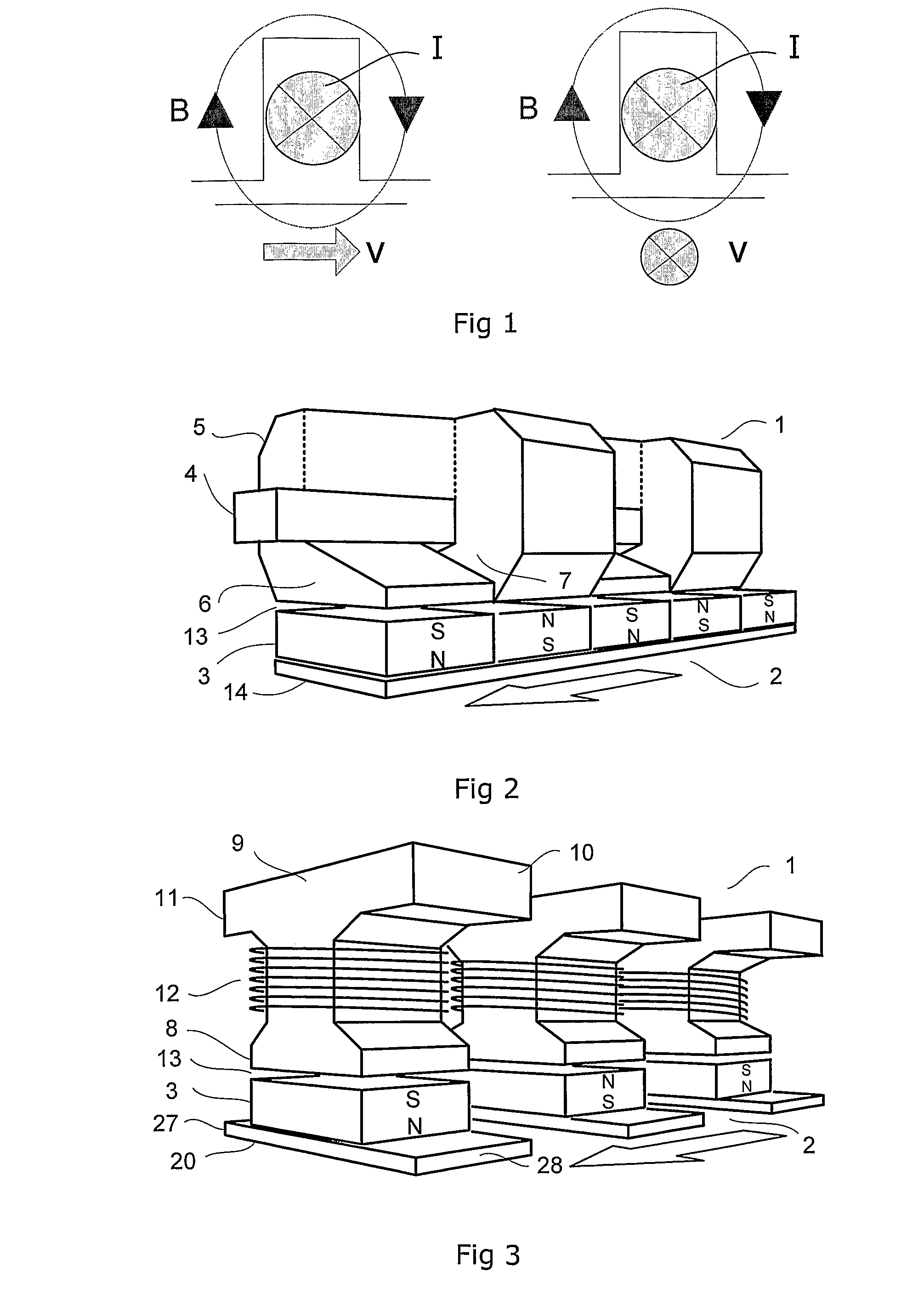
[0043]In a conventional electric machine the plane of the magnetic flux B is aligned with the plane of movement V while the plane of current I is perpendicular to both of these planes. This is shown in the left part of FIG. 1. In a transverse flux machine the plane of current I is aligned with the plane of movement V while the plane of the magnetic flux B is perpendicular to both of these planes. This is shown in the right part of FIG. 1.

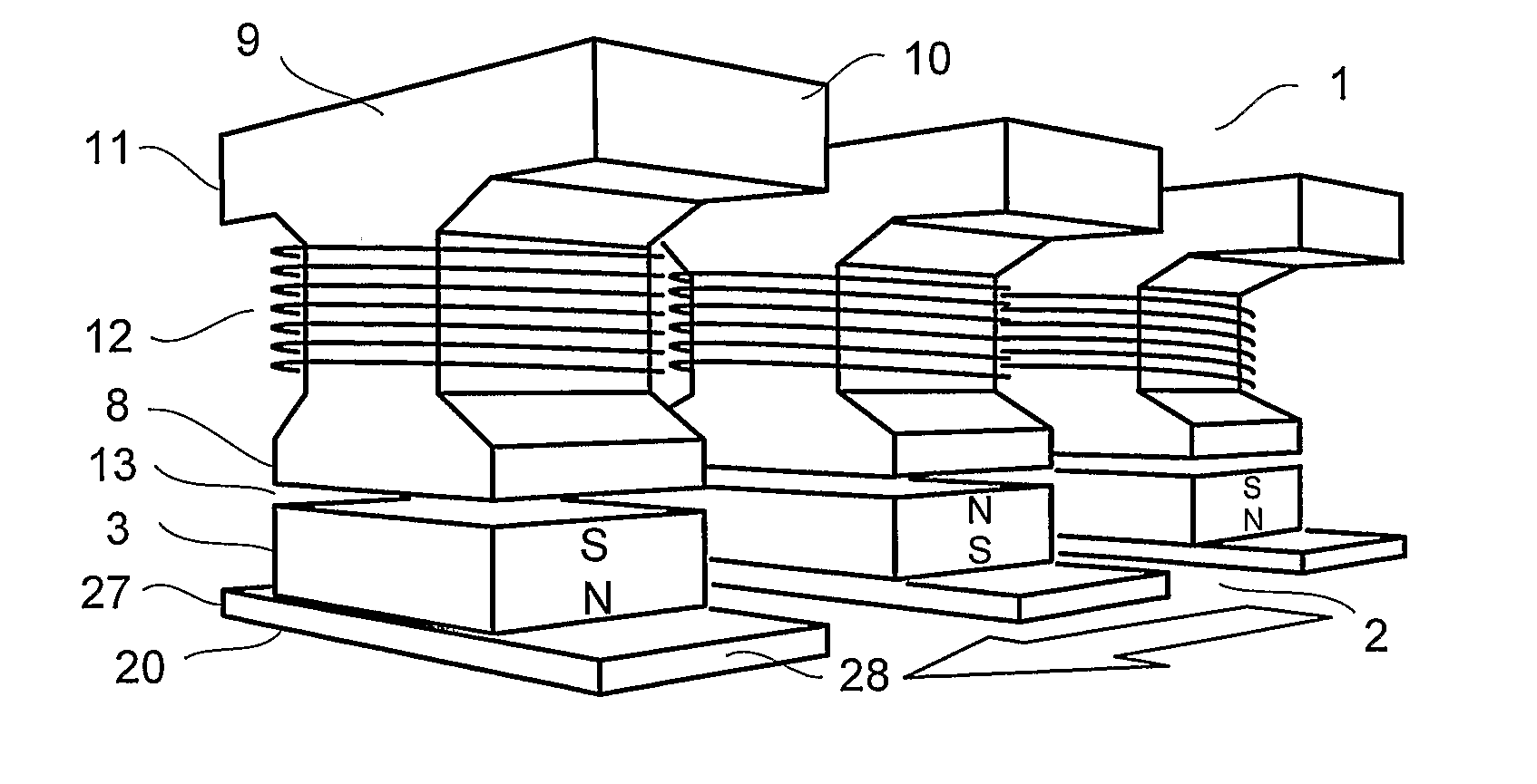
[0044]A transverse flux machine according to the prior art is shown in FIG. 2. The machine comprises a stator part 1 and a translator part 2 movable in the direction of the arrow in the lower part of FIG. 2. The translator part comprises a plurality of permanent magnets 3 arranged in a row on a magnetic flux conducting translator back 14. The magnetic flux orientation of adjacent magnets is in antiparallel with each other. The stator comprises a winding 4 and a plurality of core pieces 5. The winding comprises a plurality of strands in a bundle alig...


PUM


Abstract

A transverse flux linear machine including a first interacting part including an electric winding and a second interacting part including a plurality of magnetic poles. The first and second interacting parts are movable relative to each other and defining between them an airgap.

Description

TECHNICAL FIELD[0001]The present invention concerns a transverse flux machine. More precisely the invention concerns a machine and a method for accomplishing a linear movement with a transverse flux operation. Especially the invention concerns a transverse flux machine comprising a first and second interacting part, which are movable relatively to each other. The first part comprises an electric winding and the second part comprises a plurality of magnetic poles. The first part is often known as a stator and the second part is known as a translator. In the following text such a machine is denoted a transverse flux linear machine.BACKGROUND OF THE INVENTION[0002]In a conventional electric machine the plane of the magnetic flux is aligned with the plane of movement while the plane of current is perpendicular to both of these planes. In a transverse flux machine the plane of current is aligned with the plane of movement while the plane of the magnetic flux is perpendicular to both of t...

Claims


Application Information

Patent Timeline
Patent Type & Authority Applications(United States)
IPC IPC(8): H02K41/03
CPCH02K41/031H02K2201/12
Inventor SADARANGANI, CHANDUR
Owner ABB RES LTD
Why Eureka
Try Eureka