Dot measurement method and apparatus

a measurement method and apparatus technology, applied in the direction of printing, other printing apparatus, etc., can solve the problems of not being able to calculate the diameter of the dot and not being able to measure the deposition position of the dots at the same time, so as to achieve the effect of reducing the size of the do

Inactive Publication Date: 2008-12-18
FUJIFILM CORP
View PDF2 Cites 17 Cited by
  • Summary
  • Abstract
  • Description
  • Claims
  • Application Information

AI Technical Summary

Benefits of technology

[0012]According to the present invention, it is possible to determine the dot deposition positions and the dot diameter simultaneously (from the same captured image). Therefore, it is possible to minimize (reduce to one time) the formation of line patterns (a sample chart) for measurement and the imaging of same. Furthermore, in comparison with a method used in the related art, it is possible to achieve measurement of higher accuracy with an imaging apparatus of low resolution, and therefore the data size of the captured image can be reduced, the processing time can be shortened, and the reading time can also be shortened.

Problems solved by technology

Furthermore, the technology described in Japanese Patent Application Publication No. 2006-284406 principally calculates the dot deposition positions (dot positions), and cannot simultaneously calculate the dot diameter.
On the other hand, the technology described in Japanese Patent Application Publication No. 10-230593 is aimed at measuring the ink ejection volume, and cannot simultaneously measure the deposition positions of the dots formed by droplets ejected from the nozzles.

Method used


Image

  • Dot measurement method and apparatus
  • Dot measurement method and apparatus
  • Dot measurement method and apparatus

Examples


modification embodiment

[0310]In the embodiments described above, a line sensor is used as the imaging apparatus of the image reading apparatus, but instead of the line sensor, it is also possible to use an area sensor (surface imaging device). It is also possible to adopt a composition in which the whole of the sample chart can be imaged by means of one area sensor, or a composition in which the imaging area is divided up into separate regions, imaging is carried out for each region, and the data for the whole of the sample chart is acquired by joining together the respective regions.

[0311]FIG. 39 is a diagram showing an example in which the imaging area is divided up into a plurality of regions, and images of each of the regions are captured by means of an area sensor. More specifically, a plurality of area sensors are arranged in the paper width direction, and the direction of arrangement of the photoreceptor elements of the respective area sensors has an oblique angle with respect to the line patterns....


PUM


Abstract

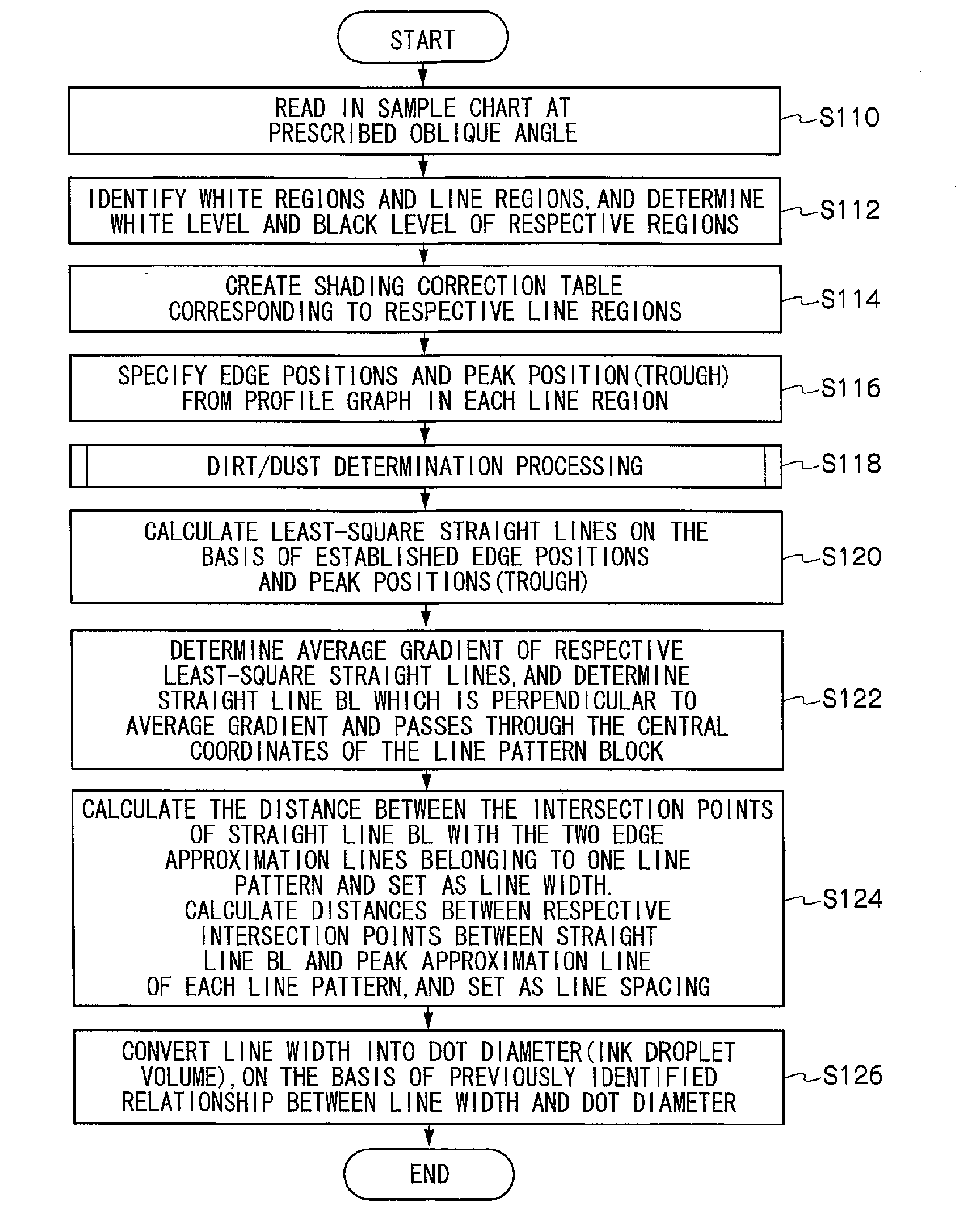
A dot measurement method includes: a line pattern forming step of forming line patterns on the ejection receiving medium; a pattern reading step of capturing an image of the line patterns; a profile graph acquiring step of acquiring profile graphs for each of the line patterns; a characteristic position calculating step of calculating extreme value positions, first edge positions and second edge positions for each of the line patterns; an approximation line calculating step of calculating a line-center approximation line, a first edge approximation line and a second edge approximation line; a line width calculating step of calculating a line width; a correlation information acquiring step of beforehand acquiring at least one of a first relationship between the line width and the dot diameter, and a second relationship between the line width and the ejection volume; and a measurement value calculating step of calculating at least one of the dot diameter and the ejection volume in accordance with the line width and the at least one of the first and second relationships.

Description

BACKGROUND OF THE INVENTION[0001]1. Field of the Invention[0002]The present invention relates to a dot measurement method and apparatus, and more particularly to technology for measuring positions and diameters of deposited dots formed by droplets ejected from a liquid ejection head, typically, an inkjet head, or for measuring the volume of the ejected liquid droplets.[0003]2. Description of the Related Art[0004]Japanese Patent Application Publication No. 2006-284406 proposes technology for determining deposition position displacement of dots formed by droplets ejected from a liquid ejection head. According to Japanese Patent Application Publication No. 2006-284406, the positions of isolated dots are measured by ejecting droplets to form isolated dots from the nozzles of a head, capturing an image of the droplet ejection result, calculating the straight line (path) traced by the respective dots, and then comparing with a reference straight line.[0005]Japanese Patent Application Publ...

Claims


Application Information

Patent Timeline
Patent Type & Authority Applications(United States)
IPC IPC(8): B41J29/393
CPCB41J29/393
Inventor YAMAZAKI, YOSHIROU
Owner FUJIFILM CORP
Why Eureka
Try Eureka