Control unit, storage unit, and method for manufacturing storage unit

a technology of storage unit and control unit, which is applied in the direction of maintaining the head carrier alignment, functional testing of recording heads, instruments, etc., can solve the problems of high probability of etc., and achieve the effect of reducing the damage to the head or the medium

Inactive Publication Date: 2008-12-18
HASBRO INC +1
View PDF10 Cites 5 Cited by
  • Summary
  • Abstract
  • Description
  • Claims
  • Application Information

AI Technical Summary

Benefits of technology

[0008]It is an object of the present technique to provide a control unit for a storage unit that can reduce damage of a head or a medium.

Problems solved by technology

However, in the technique for determining a heater setting value using the value of the TDP, a problem exists in that the probability that, for example, a head or a medium is damaged is high.
Thus, when the TDP is measured for each position on the storage medium such as a disk above which the head floats and each temperature in the unit, since the number of times the head and the medium are put in contact with each other inevitably increases, the probability that, for example, the head or the medium is damaged is high.

Method used


Image

  • Control unit, storage unit, and method for manufacturing storage unit
  • Control unit, storage unit, and method for manufacturing storage unit
  • Control unit, storage unit, and method for manufacturing storage unit

Examples


first embodiment

Components of Magnetic Disk Unit (First Embodiment)

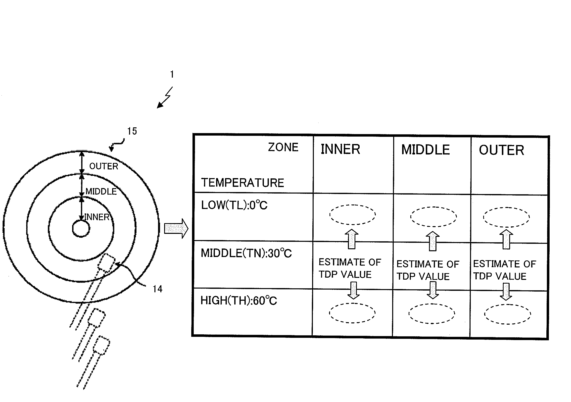
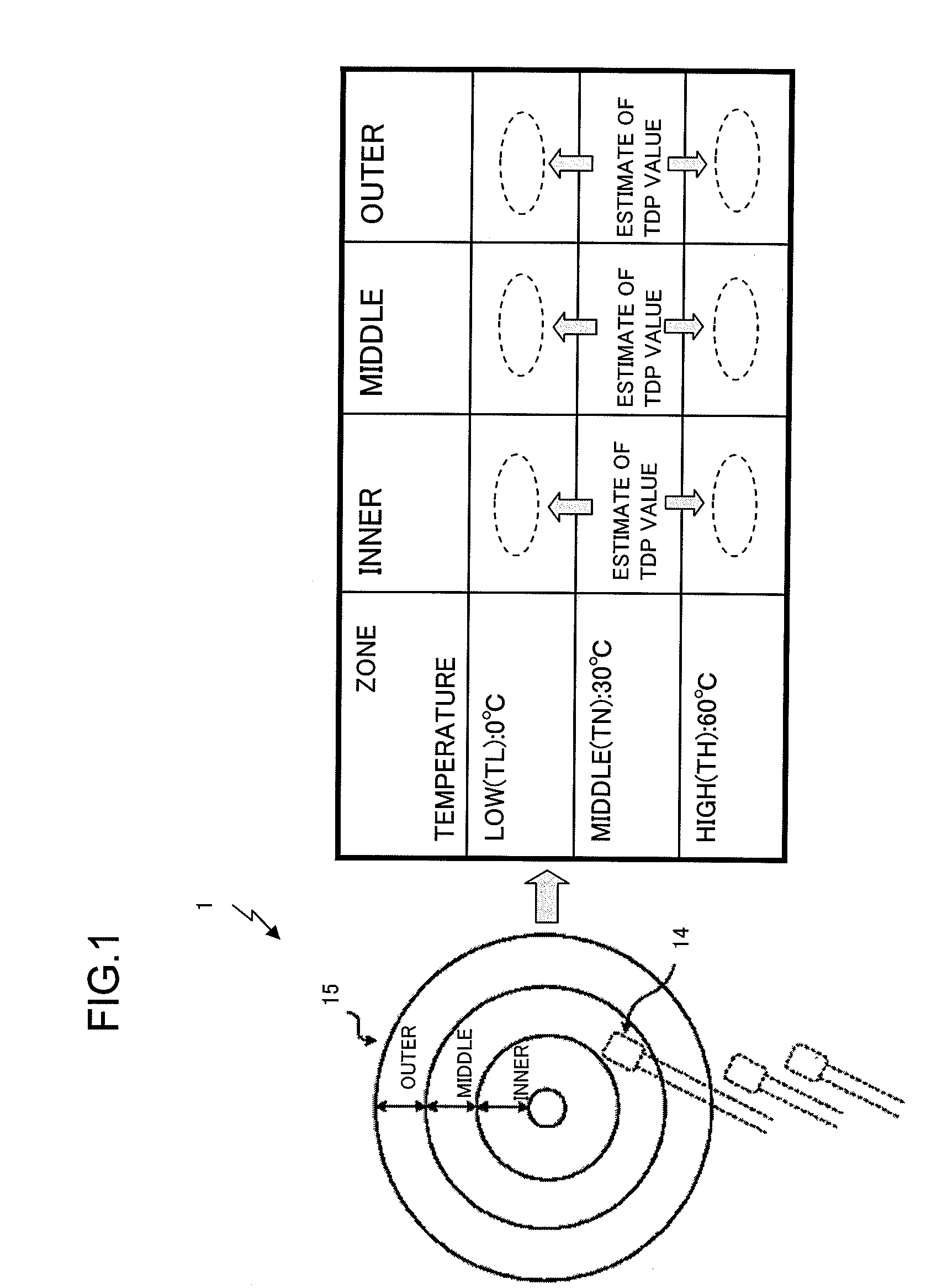
[0040]The components of the magnetic disk unit 1 according to the first embodiment will now be described using FIG. 3. FIG. 3 is a block diagram showing the components of the magnetic disk unit 1 according to the first embodiment. The magnetic disk unit 1 includes a host interface (IF) control unit 2, a buffer control unit 3, a buffer memory 4, a format control unit 5, a read channel 6, a head integrated circuit (IC) 7, a microprocessing unit (MPU) 8, a memory 9, a nonvolatile memory 10, a servo control unit 11, a voice coil motor (VCM) 12, a spindle motor (SPM) 13, heads 14, a storage medium 15, and a thermometer (not shown), and predetermined ones of the components are connected to each other via a common bus 16, as shown in FIG. 3.

[0041]The main components of the magnetic disk unit 1 according to the first embodiment will now be briefly described. The host IF control unit 2 controls communications of, for example, various types o...

second embodiment

[0063]While the first embodiment of the present technique has been described, the present technique may be implemented in various embodiments other than the first embodiment. The other embodiments of the present technique will now be described.

(1) Estimating TDP Values at Other Set Temperatures by Linear Interpolation

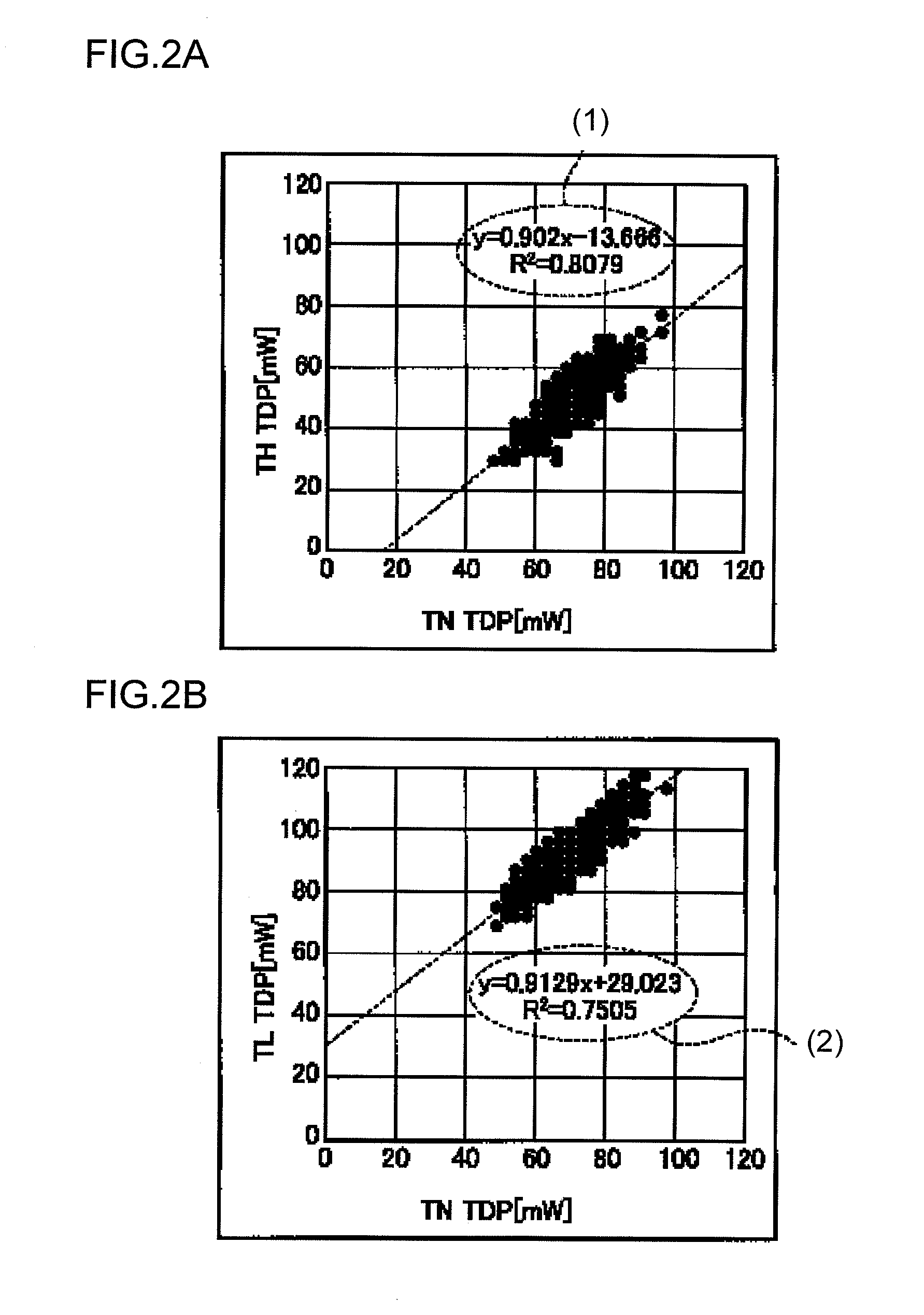
[0064]In the first embodiment, a case is described where, using conversion equations obtained from the correlation between TDP values measured in advance at individual set temperatures and TDP values that are actually measured, TDP values at set temperatures other than set temperatures at which the TDP values are actually measured are estimated. However, the present technique is not limited to the case.

[0065]Specifically, the MPU 8 may measure fourth TDP values at at least two set temperatures for each of the sub-areas (for example, inner, center, and outer sub-areas) of the storage medium 15 and perform linear interpolation in which the correlation between sixth TDP va...


PUM

PropertyMeasurementUnit
temperatureaaaaaaaaaa
poweraaaaaaaaaa
temperatureaaaaaaaaaa

Abstract

A control unit adjusts spacing between a head with a heater and a storage medium of a storage unit by controlling power of the heater. The control unit measures first values of touchdown heater power at a first temperature set as temperature condition. And the control unit estimates second values of the touchdown heater power at a temperature other than the first temperature set on the measurement of the first values, on basis of a conversion equation. And the control unit determines heater power setting values to adjust the spacing between the head and the storage medium, for each of the sub-areas, on the basis of the first values and the second values.

Description

BACKGROUND[0001]1. Field of the Technique[0002]The present technique relates to a control unit for a storage unit that determines a heater setting value for adjusting the spacing between a storage medium and a head.[0003]2. Description of the Related Art[0004]A known technique exists in a magnetic disk unit for keeping a constant distance between a disk and a head by adjusting the spacing for the head in a manner that depends on the temperature in the magnetic disk unit.[0005]In the magnetic disk unit, before the product is shipped, a heater setting value for adjusting the spacing is predetermined for each mounted head, each position on a medium such as a disk, and each temperature in the unit. In this case, a technique exists, for determining a heater setting value using an output value measured when the head and the disk are put in contact with each other (touchdown), i.e., the value of what is called a touchdown heater power (TDP).[0006]However, in the technique for determining a...

Claims


Application Information

Patent Timeline
Patent Type & Authority Applications(United States)
IPC IPC(8): G11B5/02G11B5/127
CPCG11B5/3133G11B5/40Y10T29/49025G11B5/6064G11B5/455G11B5/60G11B21/02G11B21/21
Inventor URATA, YUKIO
Owner HASBRO INC
Why Eureka
Try Eureka