
Single-chip wireless tranceiver

Active Publication Date: 2008-12-18
AVAGO TECH INT SALES PTE LTD
View PDF85 Cites 35 Cited by
  • Summary
  • Abstract
  • Description
  • Claims
  • Application Information

AI Technical Summary

Benefits of technology

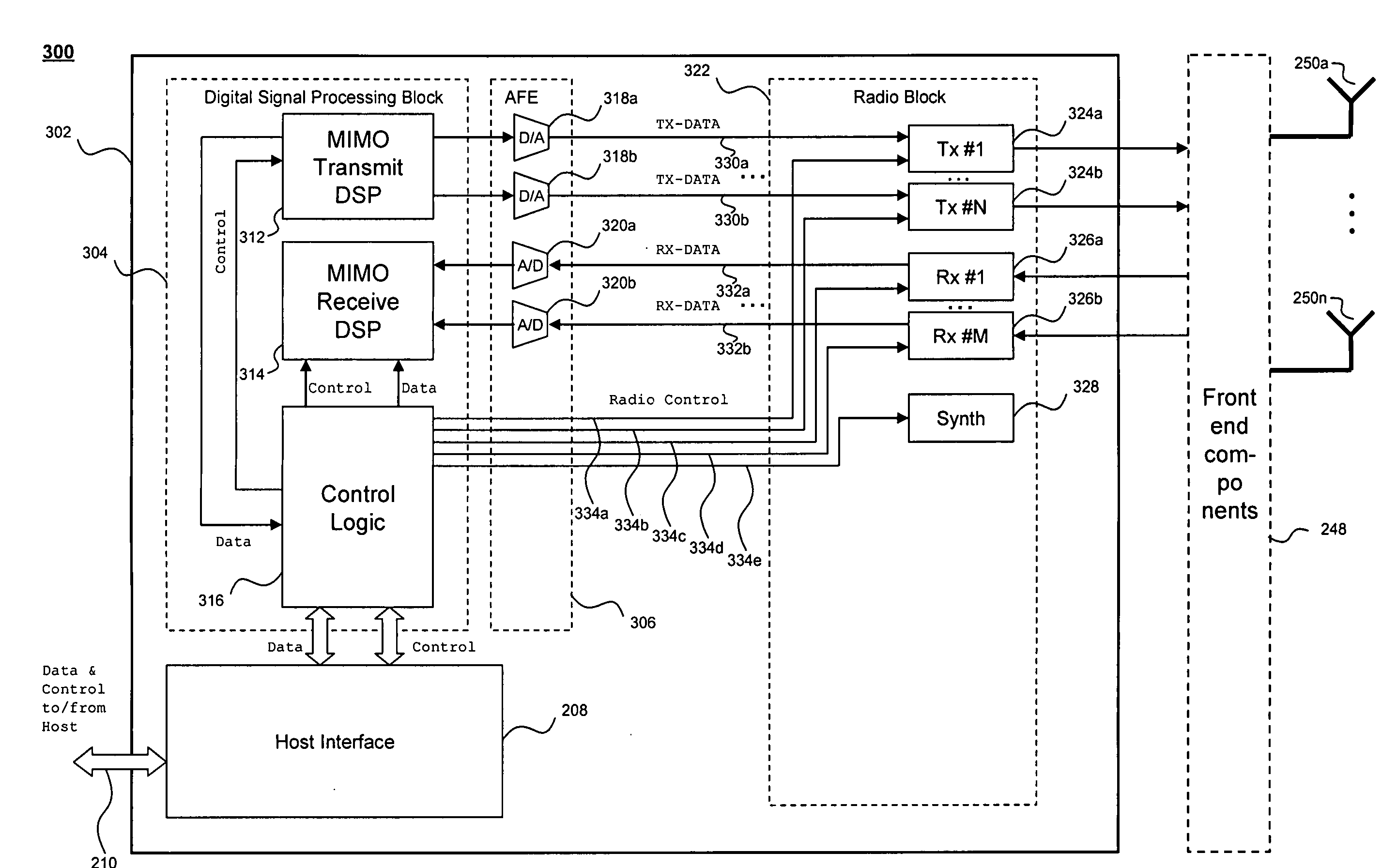
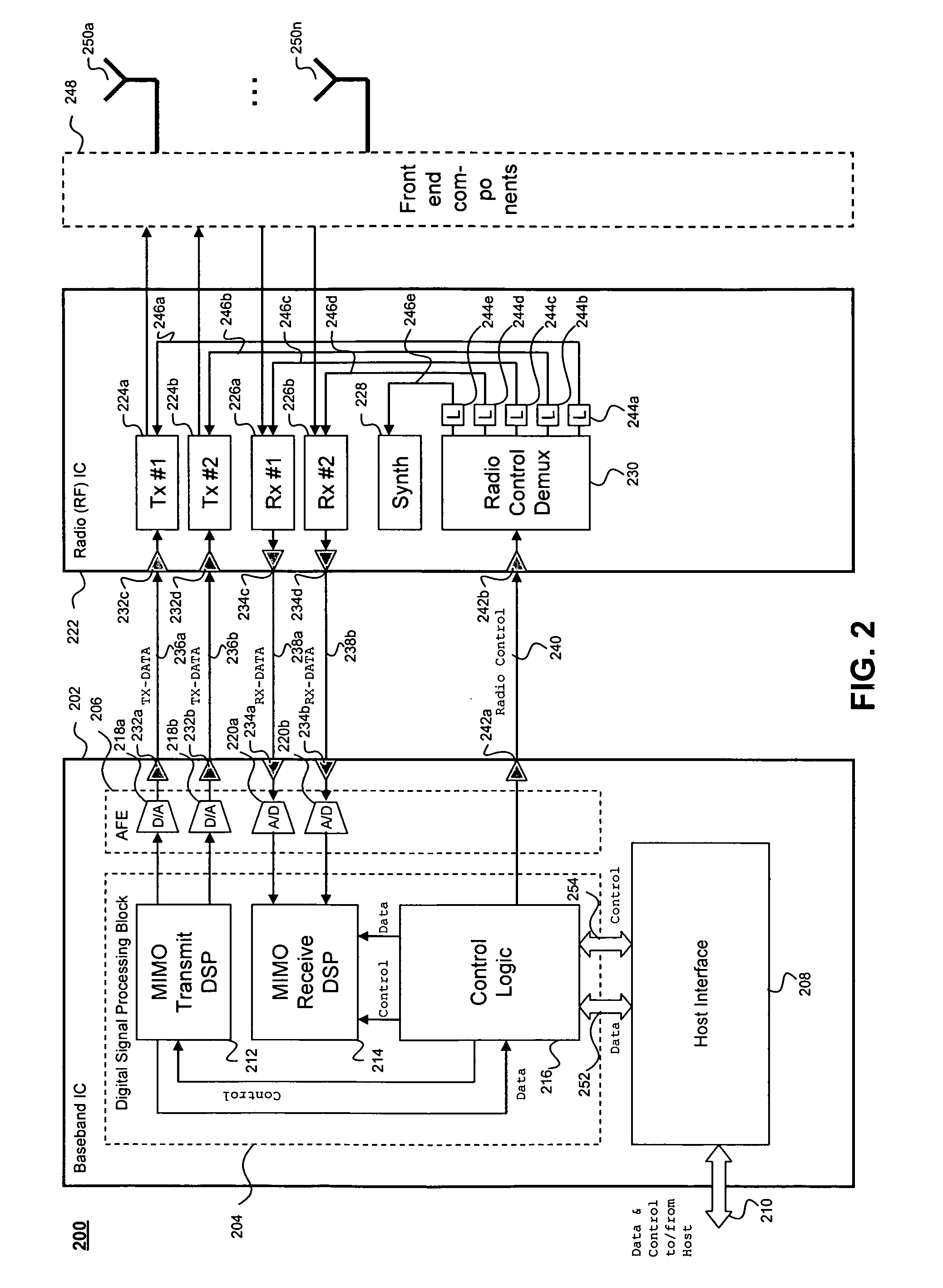
[0009]Embodiments of a wireless transceiver are provided herein. Embodiments can be used in multiple-input-multiple-output (MIMO) wireless transceivers. In an embodiment, radio control signal bundles are provided as direct parallel interconnects between digital signal processing modules and the radio module of the wireless transceiver to enable a precise low-latency control of radio functions. In another embodiment, a separate physical line is provided to control each radio setting of the radio module, thereby enabling simultaneous real-time control of any number of radio settings. In a further embodiment, the various digital and analog components of the wireless transceiver are integrated within a single chip of the same process technology.

Problems solved by technology

This degradation becomes even more stringent when more than two transmitter and / or receiver radio units are used in the wireless transceiver.

Method used


Image

  • Single-chip wireless tranceiver
  • Single-chip wireless tranceiver
  • Single-chip wireless tranceiver

Examples


Embodiment Construction

)

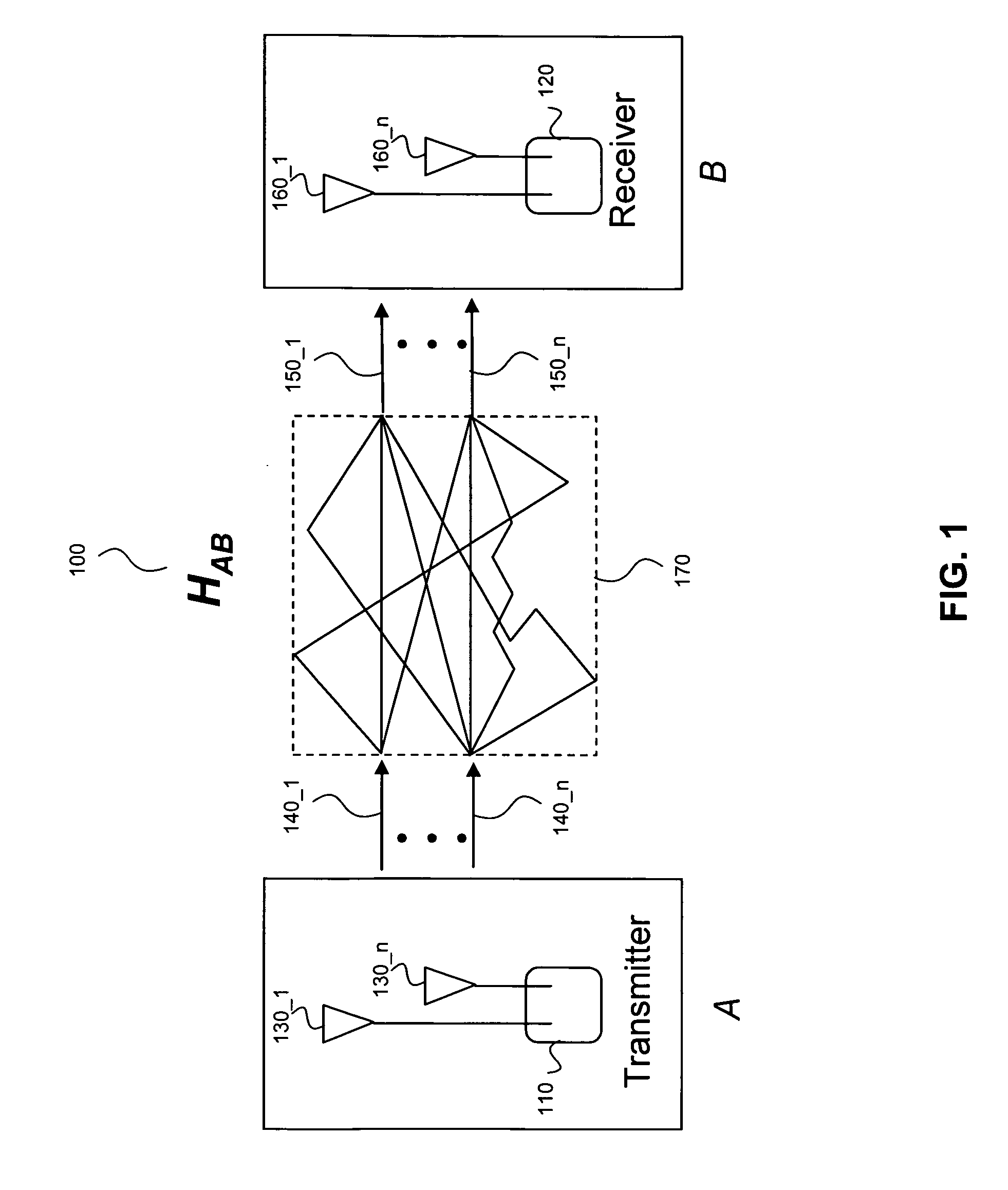
[0017]FIG. 1 illustrates an example multiple-input multiple-output (MIMO) communication system 100. Communication system 100 includes transceivers A and B and a communication channel 170.

[0018]Transceiver A includes a transmitter 110. Transceiver A may also include a receiver (not shown). Transmitter 110 includes multiple transmit antennas 130-{1, . . . ,n}. Transceiver B includes a receiver 120. Transceiver B may also include a transmitter (not shown). Receiver 120 includes multiple receive antennas 160-{1, . . . ,m}. The number of transmit antennas (n) of transmitter 110 and the number of receive antennas (m) of receiver 120 may or may not be equal.

[0019]Communication channel 170 represents a MIMO channel. Accordingly, communication channel 170 includes multiple spatial sub-channels formed between multiple transmit antennas 130-{1, . . . ,n} and multiple receive antennas 160-{1, . . . ,m}. Typically, the number of spatial sub-channels comprised in a MIMO communication channel is ...


PUM


Abstract

Embodiments of a wireless transceiver are provided. Embodiments can be used in multiple-input-multiple-output (MIMO) wireless transceivers. In an embodiment, radio control signal bundles are provided as direct parallel interconnects between digital signal processing modules and the radio module of the wireless transceiver to enable a precise low-latency control of radio functions. In another embodiment, a separate physical line is provided to control each radio setting of the radio module, thereby enabling simultaneous real-time control of any number of radio settings. In a further embodiment, the various digital and analog components of the wireless transceiver are integrated within a single chip of the same process technology.

Description

CROSS-REFERENCE TO RELATED APPLICATIONS[0001]The present application claims the benefit of U.S. Provisional Patent Application No. 60 / 929,160, filed Jun. 15, 2007 (Atty. Docket No. 2875.1610000), which is incorporated herein by reference in its entirety.BACKGROUND OF THE INVENTION[0002]1. Field of the Invention[0003]The present invention relates generally to wireless communications, and more particularly to a wireless transceiver.[0004]2. Background Art[0005]Multiple-input-multiple-output (MIMO) is a wireless communications technology that simultaneously uses multiple spatial sub-channels formed between multiple transmit antennas and multiple receive antennas to transmit signals between wireless transceivers.[0006]Accordingly, precise real-time control of radio settings in the wireless transceivers is needed to efficiently receive and recombine received signals into information signals. For example, real-time control is needed of gain stages, filter bandwidths, and power-up / down fun...

Claims


Application Information

Patent Timeline
IPC IPC(8): H04B1/44
CPCH04B7/0413H01L2924/0002H01L2924/00H04B1/16H04B7/02
Inventor HAMMERSCHMIDT, JOACHIM S.BEHZAD, ARYA REZACARTER, KEITH ANDREWSFURRER, SIMEONGAIKWAD, ROHIT VIJAYTRACHEWSKY, JASON ALEXANDERBAGCHI, AMITMOORTI, RAJENDRA TUSHARKODAVATI, VENKATESWARA RAO
Owner AVAGO TECH INT SALES PTE LTD
Learn More