
Digital communications system

a communication system and digital technology, applied in the field of digital communications systems, can solve the problems of large amount of data needed to detect and large amount of data needed to process

Inactive Publication Date: 2008-12-18
FUJITSU TOSHIBA MOBILE COMM LTD
View PDF9 Cites 10 Cited by
  • Summary
  • Abstract
  • Description
  • Claims
  • Application Information

AI Technical Summary

Benefits of technology

[0012]The present invention has been accomplished to solve the above-described problems. The object of the present invention is to provide a digital communications system capable of detecting the start position of the transmission format without processing a large amount of data even if the transmission format has a plurality of candidates for the start position.
[0015]Therefore, the present invention can provide a digital communications system capable of detecting the start position of the transmission format without processing a large amount of data even if the transmission format has a plurality of candidates for the start position.

Problems solved by technology

However, since decoding of the error-correcting code needs to be started at the start position of the transmission format, this method can be applied only to a case where the start position of the transmission format is constant and the data size is varied according to the transmission format, but not to a case where there are a plurality of start positions of the transmission format.
For this reason, if blind detection of the transmission format is executed, processing a large amount of data is needed.
In short, the conventional digital communications system has a problem that if an unknown transmission format is subjected to blind detection and the transmission format has a plurality of candidates for the start position, processing a large amount of data is needed to detect the start position.

Method used


Image

  • Digital communications system
  • Digital communications system
  • Digital communications system

Examples


first embodiment

[0052]Next, a configuration of the base station of the cellular system according to a first embodiment will be described. FIG. 5 mainly shows a configuration of a transmission system of the downstream line provided in the base station. The base station is accommodated in a mobile communications network (not shown) to connect the mobile station and the mobile communications network.

[0053]As shown in FIG. 5, the base station comprises a control unit 100, a CRC (cyclic redundancy check) adding unit 101, an error-correcting coding unit 102, a frame division unit 103, a coding rate adjusting unit 104, a modulating unit 105, a sub-carrier assigning unit 106, an IFFT (inverse fast Fourier transform) unit 107, a GI (Guard Interval) adding unit 108, a radio transmission unit 109, and a reception system 110.

[0054]The CRC adding unit 101 generates an error detection code for data sequence, with a bit length directed by a control unit 100, and adds the generated error detection code to the data...

second embodiment

[0094]Next, a configuration of the base station of the cellular system according to a second embodiment will be described. FIG. 12 mainly shows a configuration of a transmission system of the downstream line provided in the base station. The base station is accommodated in a mobile communications network (not shown) to connect the mobile station and the mobile communications network.

[0095]As shown in FIG. 12, the base station comprises a control unit 300, a CRC (cyclic redundancy check) adding unit 301, an error-correcting coding unit 302, a frame division unit 303, a coding rate adjusting unit 304, a modulating unit 305, a sub-carrier assigning unit 306, an IFFT (inverse fast Fourier transform) unit 307, a GI (Guard Interval) adding unit 308, a radio transmission unit 309, a reception system 310, a channel interleaver 311 and an in-frame interleaver 312.

[0096]The CRC adding unit 301 generates an error detection code for data sequence, with a bit length directed by a control unit 30...

third embodiment

[0145]Next, a configuration of the base station of the cellular system according to a third embodiment will be described. FIG. 19 mainly shows a configuration of a transmission system of the downstream line provided in the base station. The base station is accommodated in a mobile communications network (not shown) to connect the mobile station and the mobile communications network.

[0146]As shown in FIG. 19, the base station comprises a control unit 500, a CRC (cyclic redundancy check) adding unit 501, an error-correcting coding unit 502, a frame division unit 503, a coding rate adjusting unit 504, a modulating unit 505, a sub-carrier assigning unit 506, an IFFT (inverse fast Fourier transform) unit 507, a GI (Guard Interval) adding unit 508, a radio transmission unit 509, a reception system 510, an in-frame interleaver 512 and a shift mapping unit 513.

[0147]The CRC adding unit 501 generates an error detection code for data sequence, with a bit length directed by a control unit 500,...


PUM


Abstract

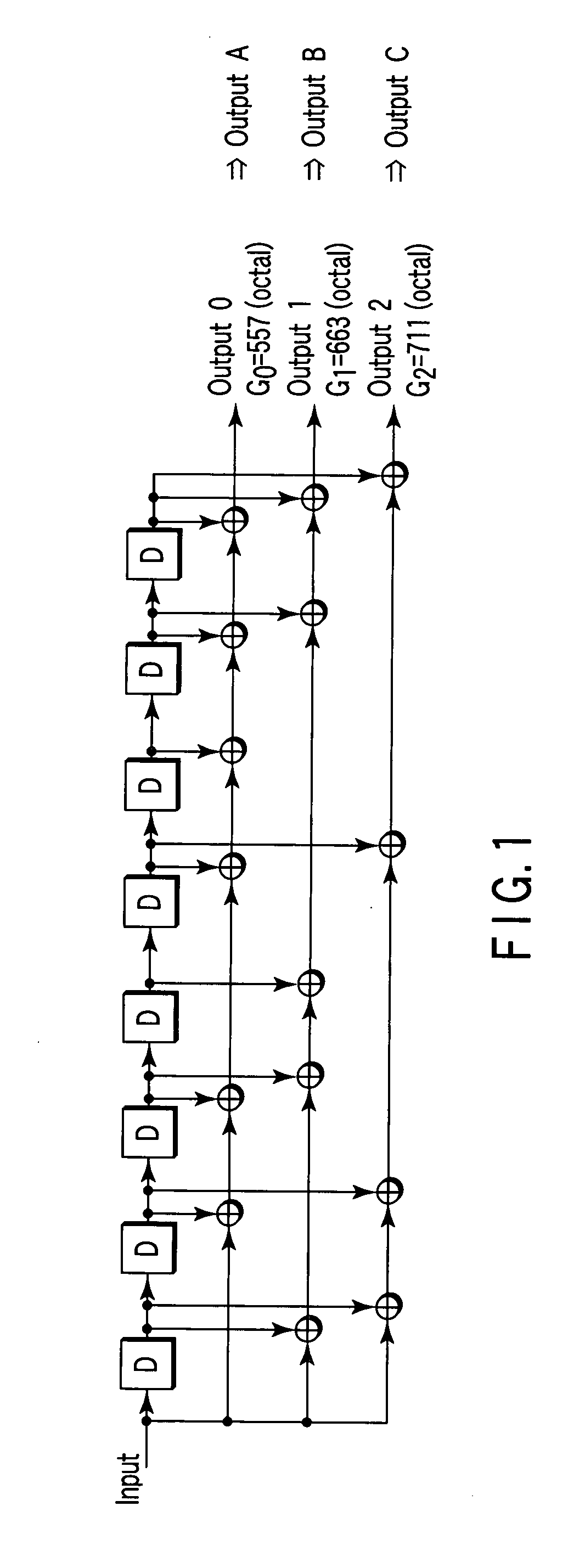
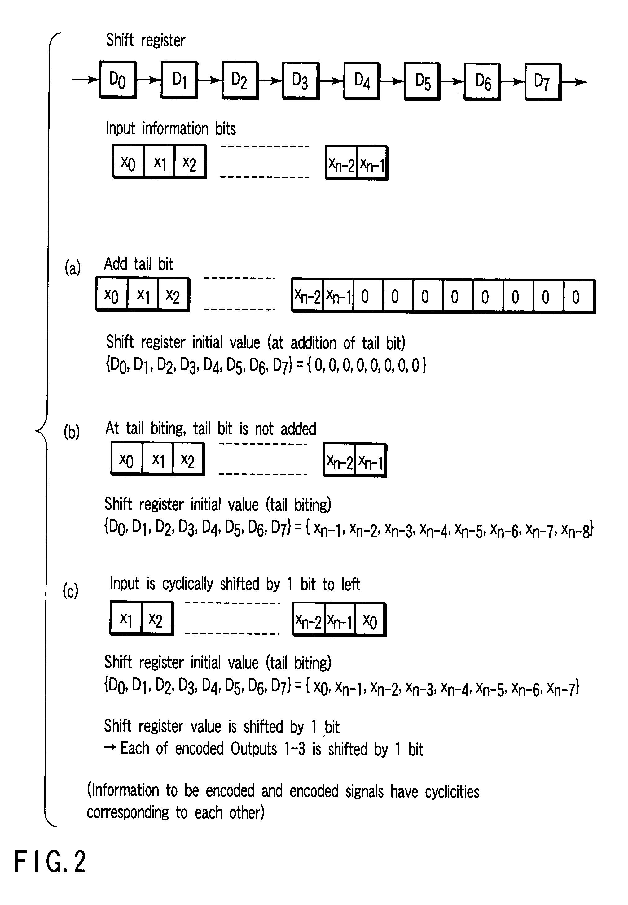
In a base station, after CRC is added to transmission data as a detection code, the transmission data is subjected to error-correcting coding using a convolutional code based on tail biting, divided into four frames of P-BCH and transmitted. For this reason, at a mobile station, even if reception (synthesis) is started from any frame of P-BCH represented as (b-1) to (b-4), a cyclic structure of the transmission signal is maintained due to the tail biting and reception data shifted by unit of frame can be obtained. For this reason, at the mobile station, even if a leading frame is unknown, decoding can be executed by one-time error-correcting decoding. A result of the decoding is subjected to CRC detection in four frame timings, the leading frame is detected and the transmission data is restored.

Description

CROSS-REFERENCE TO RELATED APPLICATIONS[0001]This application is based upon and claims the benefit of priority from prior Japanese Patent Application No. 2007-160742, filed Jun. 18, 2007, the entire contents of which are incorporated herein by reference.BACKGROUND OF THE INVENTION[0002]1. Field of the Invention[0003]The present invention relates to a digital communications system for discriminating a start position of a transmission format on a receiving side.[0004]2. Description of the Related Art[0005]In some digital communications systems, data transmission is executed by arbitrarily selecting a transmission format from a plurality of transmission format candidates. In such a system, identification information of an employed transmission format is indicated to a receiving side by a transmitting side in some cases or often is not in the other cases.[0006]In the latter cases, since the employed transmission format is not known to the receiving side, the transmission format needs to...

Claims


Application Information

Patent Timeline
Patent Type & Authority Applications(United States)
IPC IPC(8): H04L27/00
CPCH04L1/0038H04L1/0046H04L1/0054H04L1/0059H04L1/0061H04L5/0007
Inventor ASANUMA, YUTAKATERABE, SHIGEOKUROSE, KENGO
Owner FUJITSU TOSHIBA MOBILE COMM LTD
Learn More