Waste Water Lifting System

a technology of lifting system and waste water, which is applied in the direction of pump control, sewer system, positive displacement liquid engine, etc., can solve the problems of restricted or jeopardized function of float switches, and achieve the effects of convenient exchange, simple snap-fastening, and simplified manufacturing

Inactive Publication Date: 2008-12-18
KSB AG
View PDF3 Cites 0 Cited by
  • Summary
  • Abstract
  • Description
  • Claims
  • Application Information

AI Technical Summary

Benefits of technology

[0013]According to another embodiment, one or more sensors are exchangeably fastened. This can be effected by simple snap-fastening or

Problems solved by technology

However, such dynamic pressure systems, which exist in a wide variety of forms, are susceptible to the sewage water, and its constituent parts, present wi

Method used


Image

  • Waste Water Lifting System
  • Waste Water Lifting System
  • Waste Water Lifting System

Examples


Embodiment Construction

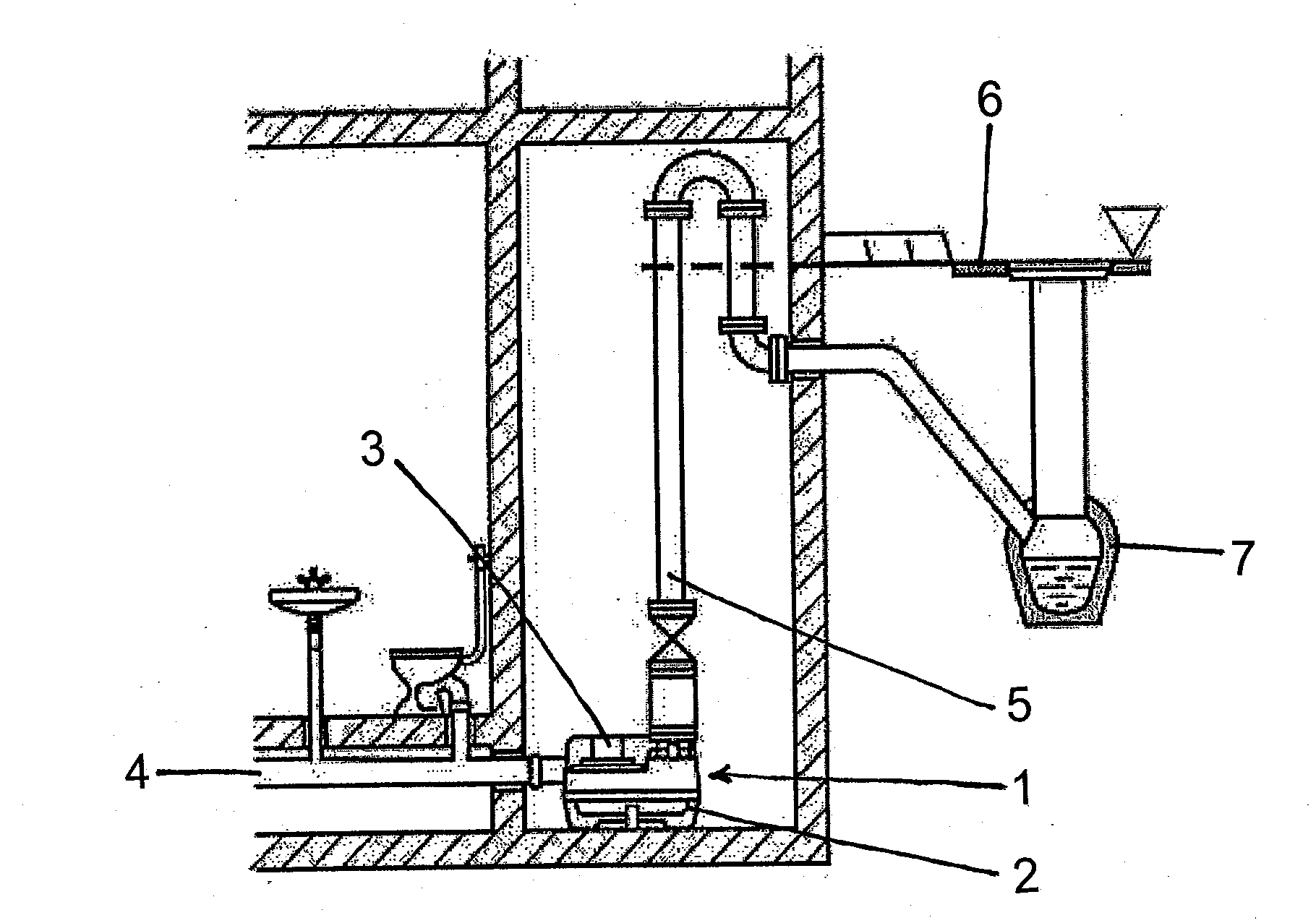
[0020]In FIG. 1, a cross section through a building is shown, in the basement of which a sanitary device is represented. Sewage from the sanitary device and other liquids to be disposed of flow to a waste water lifting system 1 and are collected therein until a sufficiently high fill level for an ad hoc conveyance is reached. The waste water lifting system 1 comprises a liquid-tight and odor-tight tank 2 and a pump 3, disposed sealingly therein, in the form of a motor pump unit, which is designed for the smooth-running conveyance of such liquids. Via an inlet pipe 4, accrued waste water is led into the tank 2, and via an outlet pipe 5 in the form of a pressure line, is conveyed over a backwash level 6 in order to flow from there into a sewage system 7. In general, such a tank 2 is provided with a ventilation (not represented here), whereby a gas evacuation is achieved and the creation of an overpressure in the tank 2 is prevented. Such a ventilation port is generally run over the ro...


PUM


Abstract

A waste water lifting system with a collecting tank (2) for liquids, in particular waste water, fecal matter, or the like, and with a device for emptying the tank, in particular a pump (3) which is connected to a motor and is arranged as a motor and pump unit in an entirely or partially recessed manner in the tank (2). The tank (2) has at least one inlet and outlet pipe (4, 5) for the liquids, and the waste water lifting system is provided with a device for switching the pump (2) on and off as a function of the liquid level (PA, PE, A) within the tank (2). The tank floor (12) or at least a partial surface thereof (12.1, 12.2) is constructed to be elastically flexible as a function of the filling level of the tank. One or more sensors (15) are arranged on the outside (14) of the elastically flexible tank floor surface (12.1, 12.2) and measure the deformation thereof. The elastically flexible tank floor part (12.1, 12.2) is arranged at a distance from an installation surface (13).

Description

CROSS REFERENCE TO RELATED APPLICATIONS[0001]This application is a continuation of international patent application no. PCT / EP2006 / 011966, filed Dec. 13, 2006, designating the United States of America, and published in German on Jun. 21, 2007 as WO 2007 / 068455, the entire disclosure of which is incorporated herein by reference. Priority is claimed based on Federal Republic of Germany patent application no. DE 10 2005 060 556.7, filed Dec. 17, 2005.BACKGROUND OF THE INVENTION[0002]The present invention relates to a waste water lifting system comprising a collecting tank for liquids, in particular sewage, excrement or the like, and comprising a device for emptying the tank, in particular a pump which is connected to a motor and which is arranged as a motor pump unit wholly or partially lowered in the tank, the tank has at least one inlet and outlet pipe, respectively, for the liquids, and the waste water lifting system is provided with a device for switching the pump as a function of ...

Claims


Application Information

Patent Timeline
IPC IPC(8): F04B49/00
CPCE03F5/22F04D15/0218
Inventor GROESCHEL, JUERGENSCHREYER, HORST
Owner KSB AG
Why Eureka
Try Eureka