
Apparatus for focusing and detecting particles in sample and method of manufacturing the same

Inactive Publication Date: 2008-12-18
SAMSUNG ELECTRONICS CO LTD
View PDF5 Cites 39 Cited by
  • Summary
  • Abstract
  • Description
  • Claims
  • Application Information

AI Technical Summary

Benefits of technology

[0011]The present invention provides an apparatus and a method of manufacturing the apparatus for focusing a particle in a sheath flow, wherein the apparatus can be easily manufactured, has excellent focusing efficiency, and optionally easily detects the focused particle.
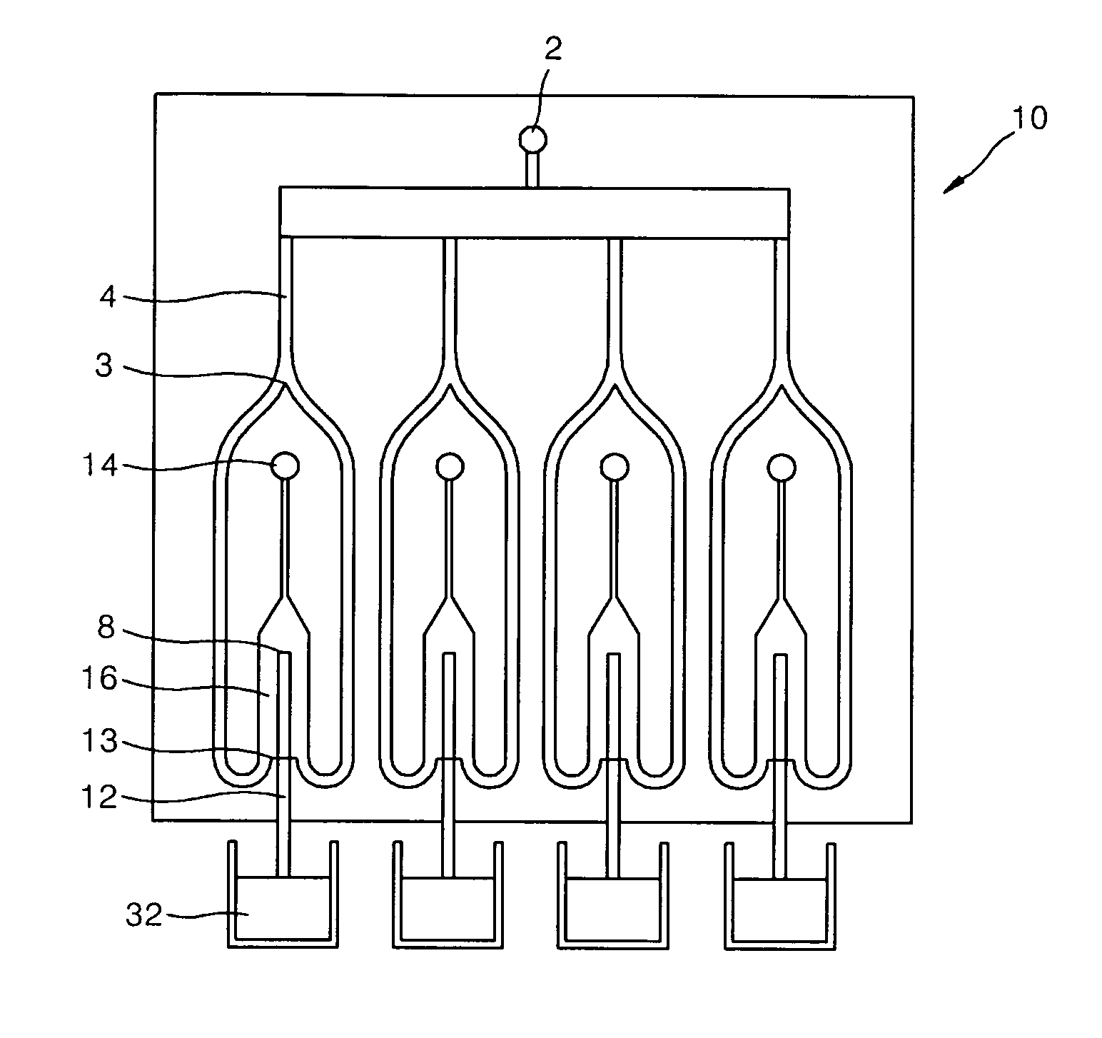
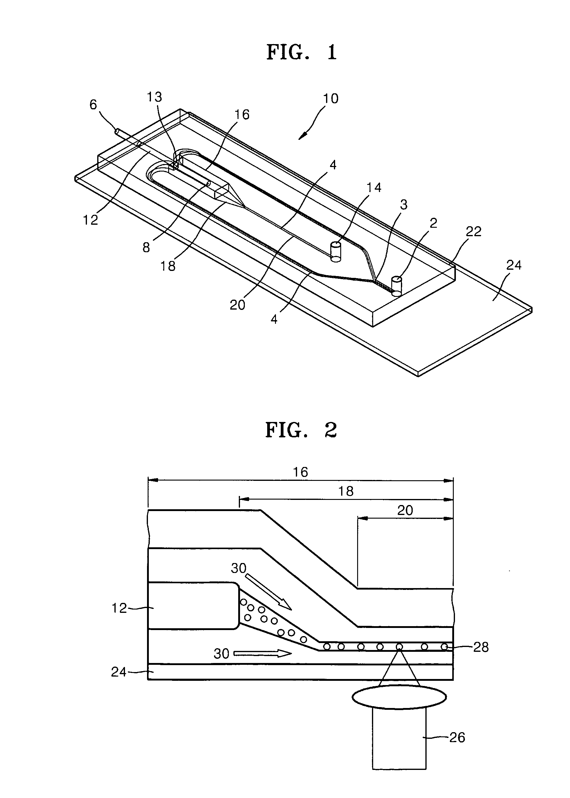
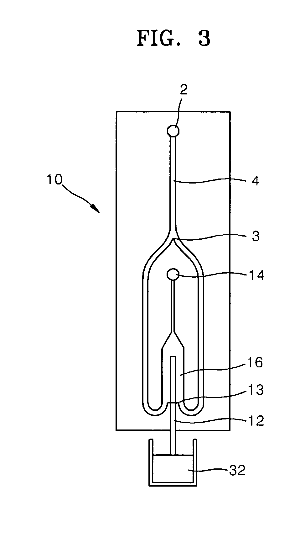
[0012]In particular, the present invention provides an apparatus for focusing a particle in a sheath flow, the apparatus comprising: a sheath fluid inlet for injecting a sheath fluid; a first flow channel for conveying a fluid, wherein the first flow channel extends from the sheath fluid inlet to the fluid outlet and is formed such that a channel extending from the sheath fluid inlet is divided into two subchannels that extend further and are then merged into one channel; and a second flow channel that extends from the sample fluid inlet to the sample fluid outlet, wherein the second flow channel is in fluid communication with the first flow channel at the merged channel region through the sample fluid outlet so as to introduce a particle in a sample into a sheath fluid conveyed through the first flow channel. The first flow channel may comprises a tapering region whose cross-sectional area decreases in a direction along which fluid flows therethrough at the merged channel region of first flow channel. The tapering region facilitates focusing of the sheath fluid around a particle. The apparatus of the present invention focuses the sheath fluid around a particle away from a side wall of surface of the first flow channel at a focusing region which is a merged channel region of the first flow channel extending downstream of the sample fluid outlet.
[0028]In the forming of the present method, a second flow channel is formed at the merged region of the first flow channel, wherein the second flow channel extends from a sample fluid inlet to a sample fluid outlet and is in fluid communication with the first flow channel at the merged channel region through the sample fluid outlet. The second flow channel may be easily formed at the merged region of the first flow channel by simply making a hole and inserting a tube into the merged channel region of the first flow channel.

Problems solved by technology

Conventional devices that have been employed to implement sheath flow have relatively complex designs and are relatively difficult to fabricate.
Therefore, it is difficult to uniformly control the flow velocity of particles (refer to FIG. 9A).
In addition, the particles close to the up and down wall surfaces of the channel may hardly flow so that it is not preferable to use the two-dimensional channel structure.
In addition, when being detected, the particles are positioned at different depths so that when a high magnification objective lens is used, it is difficult to position the particles within the focus of the lens.
However, disadvantages still exist in that it remains difficult to manufacture and use a sheath flow device.
In addition, focusing particles in a sample and detecting the focused particles remain difficult.

Method used


Image

  • Apparatus for focusing and detecting particles in sample and method of manufacturing the same
  • Apparatus for focusing and detecting particles in sample and method of manufacturing the same
  • Apparatus for focusing and detecting particles in sample and method of manufacturing the same

Examples


Embodiment Construction

[0039]The present invention will now be described more fully with reference to the accompanying drawings, in which exemplary embodiments of the invention are shown.

[0040]It will be understood that when an element is referred to as being “on” another element, it can be directly on the other element or intervening elements may be present therebetween. In contrast, when an element is referred to as being “disposed on” or “formed on” another element, the elements are understood to be in at least partial contact with each other, unless otherwise specified.

[0041]The terminology used herein is for the purpose of describing particular embodiments only and is not intended to limit the invention. As used herein, the singular forms “a”, “an” and “the” are intended to include the plural forms as well, unless the context clearly indicates otherwise. The use of the terms “first”, “second”, and the like do not imply any particular order but are included to identify individual elements. It will be ...


PUM

PropertyMeasurementUnit
Angleaaaaaaaaaa
Angleaaaaaaaaaa
Areaaaaaaaaaaa

Abstract

An apparatus for focusing a particle in a sheath flow, the apparatus comprising: a sheath fluid inlet for injecting a sheath fluid; a first flow channel for conveying a fluid, wherein the first flow channel extends from the sheath fluid inlet to the fluid outlet and is formed such that a channel extending from the sheath fluid inlet is divided into two subchannels that extend further and are then merged into one channel; and a second flow channel that extends from the sample fluid inlet to the sample fluid outlet, wherein the second flow channel is in fluid communication with the first flow channel at the merged channel region through the sample fluid outlet so as to introduce a particle in a sample into a sheath fluid conveyed through the first flow channel.

Description

[0001]This application claims priority to Korean Patent Application No. 10-2007-0058572, filed on Jun. 14, 2007, and all the benefits accruing therefrom under 35 U.S.C. §119, the contents of which in its entirety are herein incorporated by reference.BACKGROUND OF THE INVENTION[0002]1. Field of the Invention[0003]The present invention relates to an apparatus for focusing a particle in a sheath flow and a method of manufacturing the same.[0004]2. Description of the Related Art[0005]Sheath flow is a particular type of laminar flow in which one layer of fluid, or a particle, is surrounded by another layer of fluid on more than one side. The process of confining a particle stream in a fluid is referred to as a ‘sheath flow’ configuration. For example, in sheath flow, a sheath fluid may envelop and pinch a sample fluid containing a number of particles. The flow of the sheath fluid containing particles suspended therein may be narrowed almost to the outer diameter of particles in the cente...

Claims


Application Information

Patent Timeline
IPC IPC(8): G01N21/01B32B38/10B01L11/00B01L99/00
CPCG01N15/1404G01N15/1484G01N2015/1413Y10T156/1002B01L2200/0636B01L2200/0652B01L2300/0816B01L3/502776G01N21/00B01F25/00
Inventor KIM, SUHYEONHUH, NAM
Owner SAMSUNG ELECTRONICS CO LTD
Learn More