HVAC air distribution system

a technology of air distribution system and conditioned air, which is applied in the direction of ventilation system, lighting and heating apparatus, heating type, etc., can solve the problems of increasing the backpressure of the air distribution system, and the current system lacks the ability to sufficiently change the flow parameters of the room, so as to eliminate the temperature gradient

Inactive Publication Date: 2008-12-18
GLACIER BAY
View PDF13 Cites 24 Cited by
  • Summary
  • Abstract
  • Description
  • Claims
  • Application Information

AI Technical Summary

Benefits of technology

[0008]In another embodiment of the present invention, there is a method of delivering conditioned air in an HVAC system as described above or below, wherein the second routing ratio is substantially different from the first routing ratio. In another embodiment of the present invention, there is a method of delivering conditioned air in an HVAC system as described above or below, further comprising sensing the environmental condition within the first room at two substantially different sensed altitudes within the room, wherein the environmental condition is air temperature, analyzing the sensed environmental condition and determining that a temperature gradient exists between the two substantially different sensed altitudes within the room, identifying a value of a control routing ratio to be used as the second routing ratio that will, within a desired period of time, substantially eliminate the temperature gradient between the two substantially different sensed altitudes; and using the control routing ratio as the second routing ratio.

Problems solved by technology

Current systems that supply conditioned air to multiple vent locations suffer from a number of problems.
For example, control of airflow through the system is accomplished by restricting the flow of air, which increases the backpressure of the air distribution system.
Moreover, current systems lack the ability to sufficiently change flow parameters into rooms when switching between a heating and cooling mode in a system that provides both heating and cooling, such as in a reverse-cycle heat pump.
This lack of flexibility dictates that the during the original installation, the choice must be made whether to install the discharge vents high in a room (thereby maximizing comfort during cooling mode) or to install them low in the room (thus maximizing comfort when in heating mode).

Method used


Image

  • HVAC air distribution system
  • HVAC air distribution system
  • HVAC air distribution system

Examples


Embodiment Construction

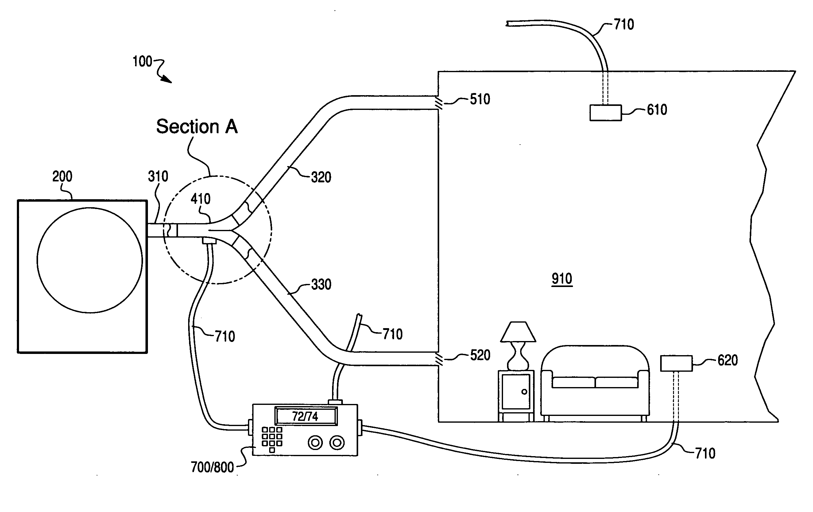
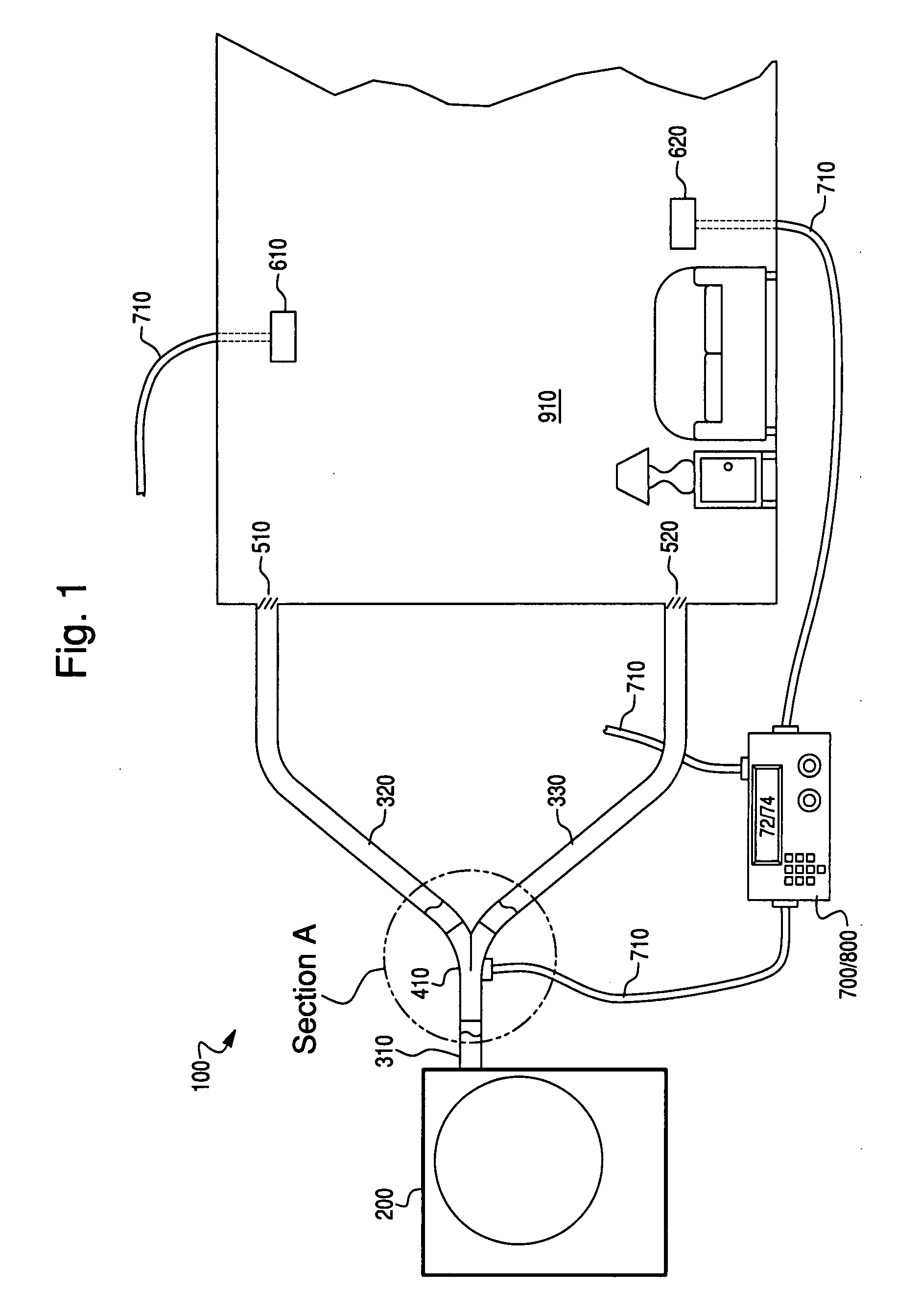
[0016]In a first exemplary embodiment of the present invention, there is a forced-air HVAC system 100 comprising a heater / cooler unit 200 configured to variously heat and cool air (i.e., to output / produce conditioned air). The unit 200 includes a fan or blower (not shown) that generates an airflow out of the unit 200 to move the heated / cooled air through the HVAC system. In some embodiments, the unit 200 may be an integral unit, such as a heat pump, in which one cycle is a cooling cycle and another cycle (a reversed cycle) is a heating cycle. In yet other embodiments, the unit 200 includes a heating element and a separate cooling element such as may be found in a central air system. The HVAC system 100 includes an outlet duct 310 that extends between the heater / cooler unit 200 and a first diverter valve 410.

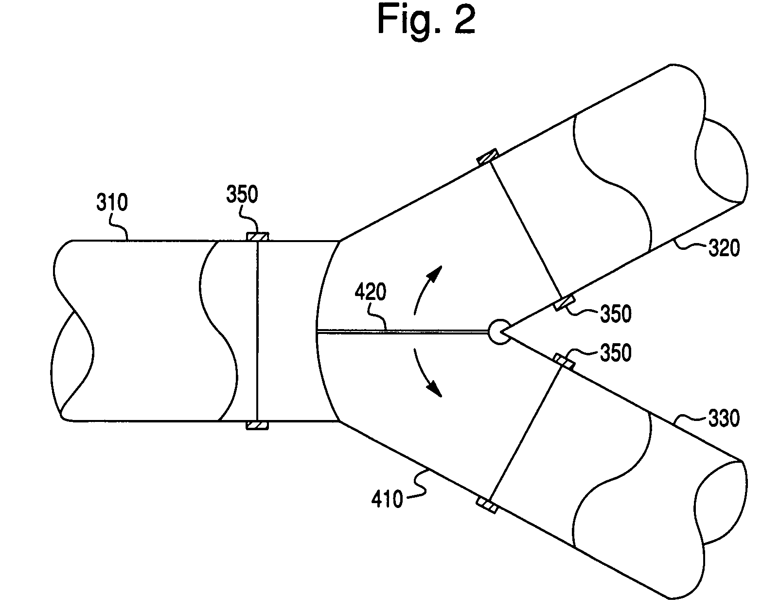
[0017]The diverter valve 410 in the embodiment shown in FIG. 1 is a Y valve, where the valve 410 splits the airflow traveling through duct 310 from heater / cooler unit 200 into tw...


PUM


Abstract

An HVAC system including a first diverter valve configured to divert, in varying amounts, an airflow entering the valve out two different outlets, in a manner that does not create a substantial increase in backpressure due to the diversion or otherwise substantially restrict the general flow of air in the HVAC system. The system further includes a first sensor assembly configured to sense a first environmental condition that includes at least one of temperature and a phenomenon indicative of the makeup of room air, a control unit, and a user interface unit, wherein the control unit is in communication with the diverter valve and the first sensor assembly.

Description

BACKGROUND OF THE INVENTION[0001]Current HVAC systems come in a wide variety of configurations. These configurations vary greatly in cost, efficiency and their ability to provide consistently accurate temperature, humidity and ventilation control, simultaneously, to multiple vent locations. The ability to accurately control these parameters is desirable as it increases the comfort of the occupants and may, under certain conditions, increase the potential for energy savings.[0002]Current systems that supply conditioned air to multiple vent locations suffer from a number of problems. For example, control of airflow through the system is accomplished by restricting the flow of air, which increases the backpressure of the air distribution system. This increase in pressure reduces the flow rate of the fan and the overall efficiency of the HVAC system. Moreover, current systems lack the ability to sufficiently change flow parameters into rooms when switching between a heating and cooling ...

Claims


Application Information

Patent Timeline
Patent Type & Authority Applications(United States)
IPC IPC(8): F24F13/10
CPCF24F11/0012F24F11/0078F24F13/10F24F11/30F24F2110/10F24F11/79F24F11/76F24F11/46F24F11/63
Inventor ALSTON, GERALD ALLENTAYLOR, MACHIKODOBBS, JUSTIN RICHARD
Owner GLACIER BAY
Why Eureka
Try Eureka