Determination of wire metric for delivery of power to a powered device over communication cabling

a technology of communication cabling and wire metric, which is applied in the field of power over local area networks, can solve the problems of limited maximum current capability of ieee 802.3at task force, no provision, no provision, etc., and achieve the effect of effective resistance and maximum safe current carrying capability

Inactive Publication Date: 2008-12-18
MICROSEMI
View PDF13 Cites 40 Cited by
  • Summary
  • Abstract
  • Description
  • Claims
  • Application Information

AI Technical Summary

Benefits of technology

[0015]Accordingly, it is a principal object of the present invention to overcome the disadvantages of the prior art by providing power from a PSE to a PD over communication cabling with current limits set at the PSE responsive to the current carrying capability of the communication cabling. In particular, the length of cable between the power sourcing equipment and powered device is determined and the effective resistance between the PSE and the PD is further determined. A metric, such as the diameter, the effective resistance per unit length and / or the maximum safe current carrying capability of the constituent wires of the communication cabling connecting the PSE and the PD is calculated. Current limits are instituted, and power is delivered, from the PSE to the PD responsive to the calculated metric.

Problems solved by technology

The above mentioned standard defines a maximum current level for delivery over the communication cabling, primarily as a result of a limit in allowable temperature rise of the communication cabling caused by power lost due to the cable resistance.
The maximum current capability of the IEEE 802.3at task force is similarly limited by an allowable maximum temperature rise of the communication cabling which is a function of the power dissipated across the conductor.
However, no provision is made in the above subject patent application for adjusting current levels and limits between the PSE and the PD responsive to the determined effective resistance.
However, no provision is made in the above subject patent application for adjusting current levels and limits between the power sourcing equipment and the powered device responsive to the determined effective resistance.
The decrease in signal amplitude technique, in particular, assumes knowledge of the actual type of cable being measured, which unfortunately requires a difficult physical inspection.
The technique disclosed assumes knowledge of the actual type of cable being measured, which unfortunately requires a difficult physical inspection.

Method used


Image

  • Determination of wire metric for delivery of power to a powered device over communication cabling
  • Determination of wire metric for delivery of power to a powered device over communication cabling
  • Determination of wire metric for delivery of power to a powered device over communication cabling

Examples


first embodiment

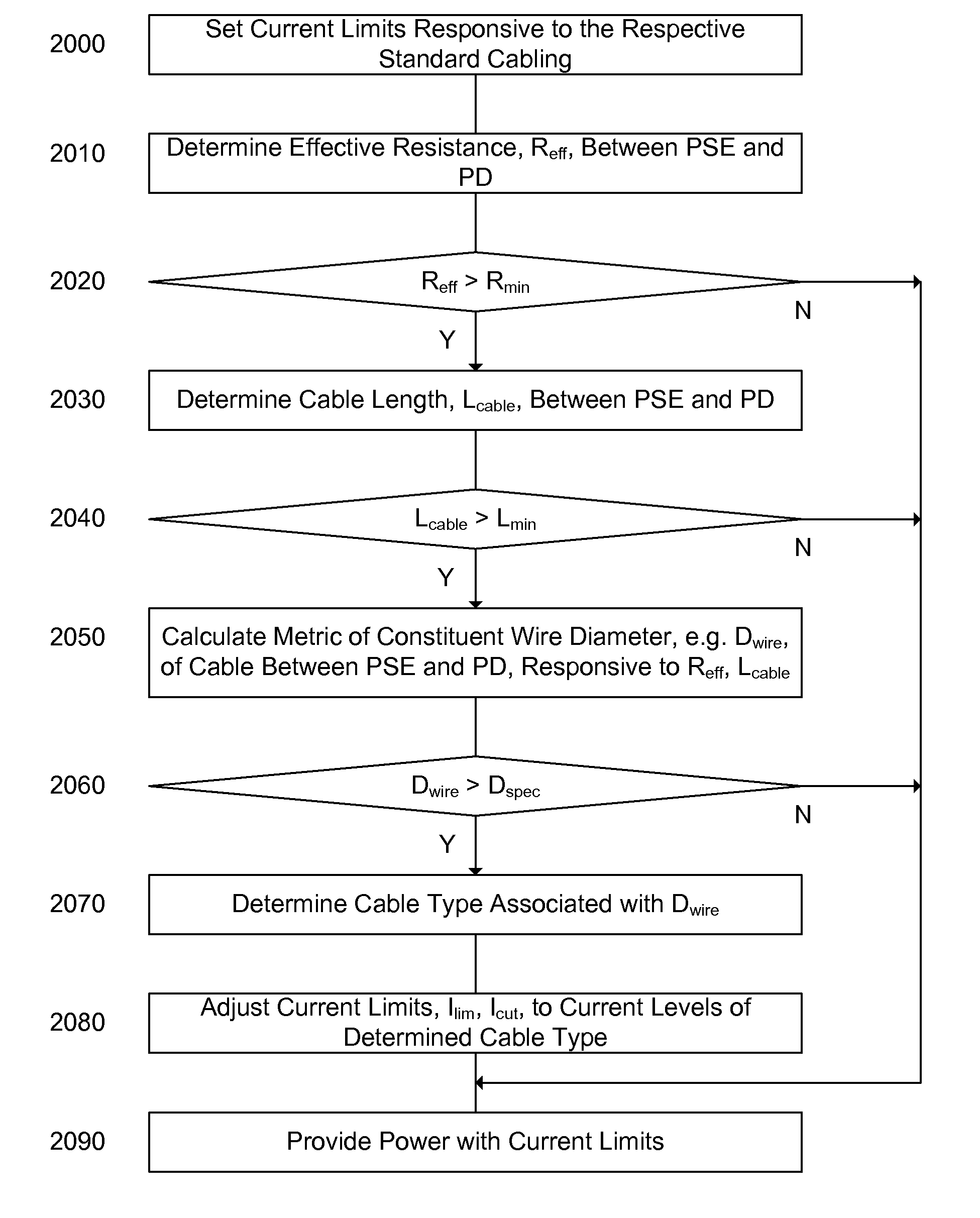
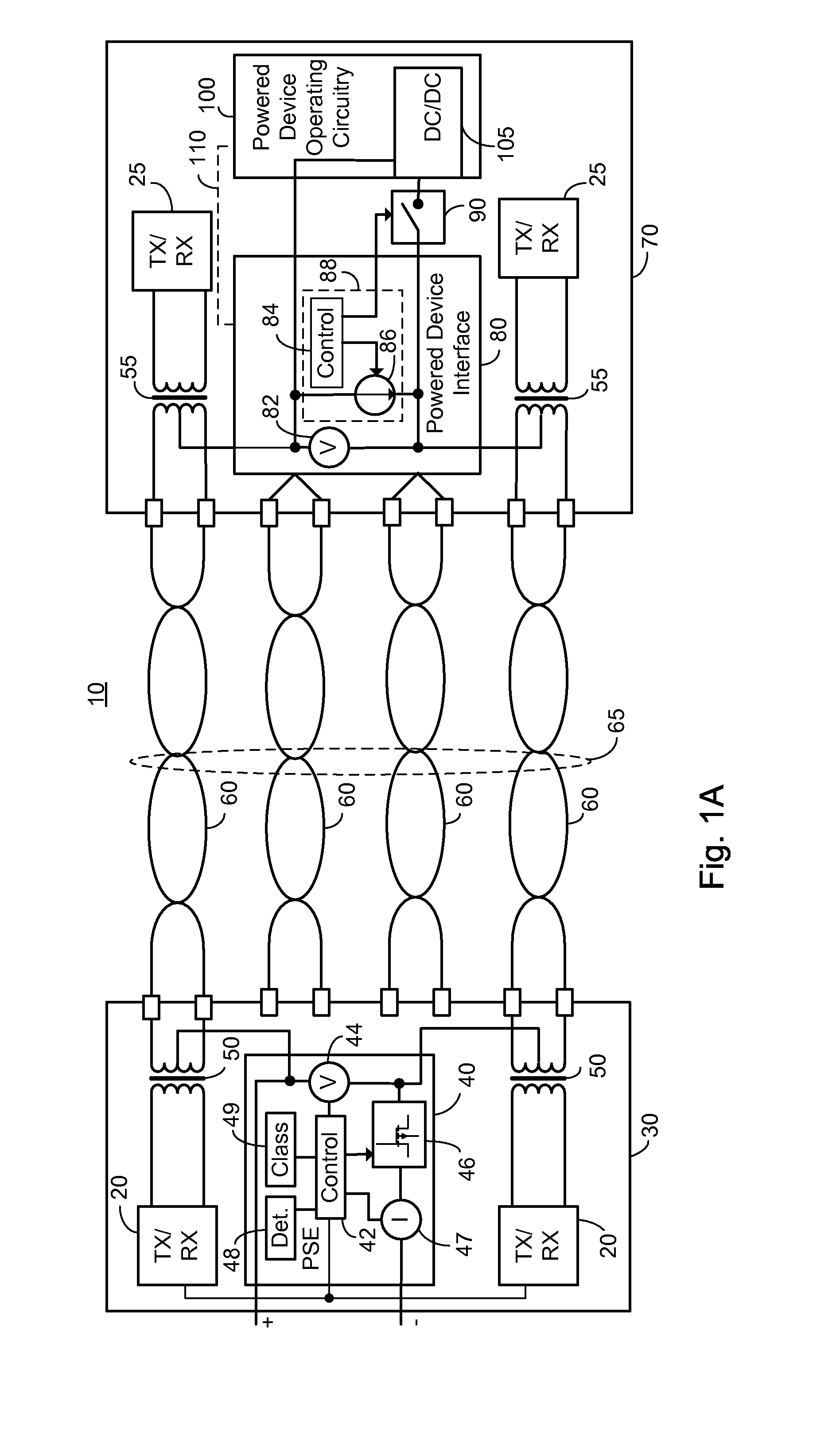
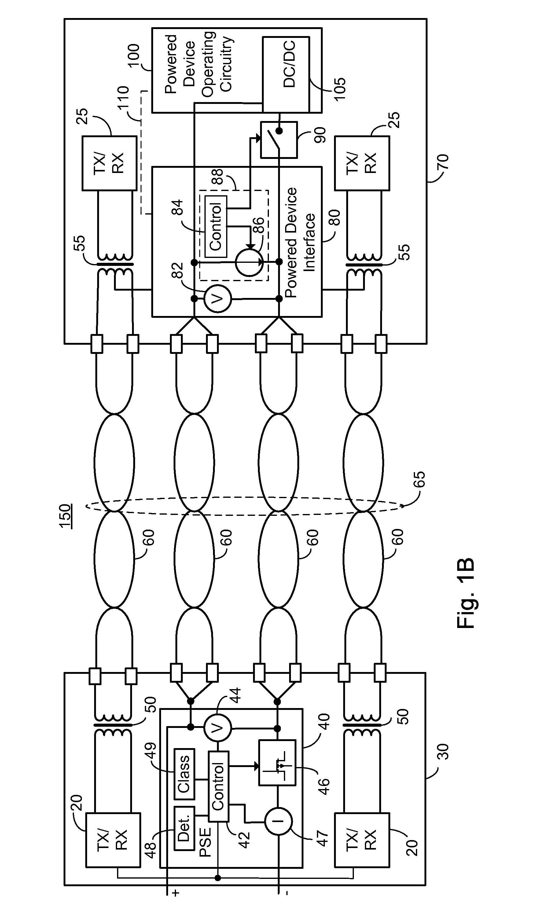
[0067]FIG. 4 illustrates a high level flow chart of the operation of PSE 40 of any of systems 10, 150 of FIGS. 1A-1B to power a PD responsive to a calculated metric of the constituent wires of communication cabling 65. In stage 2000, initial current limits for electronically controlled current limiter and switch 46 are set in accordance with the appropriate respective standard, such as without limitation one of IEEE 802.3af and the developing IEEE 802.3at standard which are based on the safe current carrying capabilities of a particular minimum cabling. In the event power is required to be delivered from PSE 40 to PD 70 in order to determine the cable length and / or the effective resistance between PSE 40 and PD 70, power is provided in accordance with the initial current limits of stage 2000.

[0068]In stage 2010, the effective resistance between PSE 40 and PD 70, denoted Reff, is determined, as described above in relation to FIGS. 2, 3 and Eq. 1. Control circuitry 42, in cooperation ...

second embodiment

[0075]FIG. 5 illustrates a high level flow chart of the operation of PSE 40 of any of systems 10, 150 of FIGS. 1A-1B to power a PD responsive to a calculated metric of the constituent wires of communication cabling 65 in accordance with a principle of the current invention. In stage 3000, initial current limits for electronically controlled current limiter and switch 46 are set in accordance with the appropriate respective standard, such as without limitation one of IEEE 802.3af and the developing IEEE 802.3at standard, which are each based on a particular minimum cabling type. In the event power is required to be delivered from PSE 40 to PD 70 in order to determine the cable length and / or the effective resistance between PSE 40 and PD 70, power is provided in accordance with the initial current limits of stage 3000.

[0076]In stage 3010, the effective resistance between PSE 40 and PD 70, denoted Reff, is determined, as described above in relation to FIGS. 2, 3 and Eq. 1. Control circ...


PUM


Abstract

A method of powering from a power sourcing equipment to a powered device over communication cabling, the method comprising: determining the effective resistance between a power sourcing equipment and a powered device; determining the length of communication cabling between the power sourcing equipment and the powered device; calculating a metric of the constituent wires of the communication cabling between the power sourcing equipment and the powered device responsive to the determined effective resistance and the determined length of communication cabling; and setting current limits for the powering of the powered device from the power sourcing equipment responsive to the calculated metric. In one embodiment the metric is one of a cross-sectional, an effective resistance per unit length and a current carrying capability of the constituent wires.

Description

BACKGROUND OF THE INVENTION[0001]The invention relates generally to the field of power over local area networks, particularly Ethernet based networks, and more particularly to a method of determining the current limits applicable for powering a powered device over communication cabling.[0002]The growth of local and wide area networks based on Ethernet technology has been an important driver for cabling offices and homes with structured cabling systems having multiple twisted wire pairs. The structured cable is also known herein as communication cabling and typically comprises four twisted wire pairs. In certain networks only two twisted wire pairs are used for communication, with the other set of two twisted wire pairs being known as spare pairs. In other networks all four twisted wire pairs are used for communication. The ubiquitous local area network, and the equipment which operates thereon, has led to a situation where there is often a need to attach a network operated device fo...

Claims


Application Information

Patent Timeline
Patent Type & Authority Applications(United States)
IPC IPC(8): G06F1/26H04L12/44
CPCG06F1/266H04L12/10
Inventor DARSHAN, YAIR
Owner MICROSEMI
Why Eureka
Try Eureka