Infusion flow guidewire system

a guidewire and flow technology, applied in the field of mechanical thrombolysis and catheter directed thrombolysis, can solve the problems of difficult to deliver the jet body through such a misshaped lumen, difficult to achieve two-part configuration for delivery to access and treat the site, and interventionists are never comfortable giving up their wire position, etc., to achieve substantial thrombolysis/fibrinolysis infusion effect and deliverable infusion

Active Publication Date: 2008-12-18
BOSTON SCI LTD
View PDF99 Cites 51 Cited by
  • Summary
  • Abstract
  • Description
  • Claims
  • Application Information

AI Technical Summary

Benefits of technology

[0008]The general purpose of the present invention is to provide a highly deliverable infusion flow guidewire having a substantial thrombectomy / fibrinolytic infusion effectiveness.

Problems solved by technology

Generally, this two-part configuration for delivery to access and treat the site was difficult to accomplish.
On occasions, the microcatheter would ovalize or otherwise distort in a tortuous anatomy, thus making it difficult to deliver the jet body through such a misshaped lumen.
Furthermore, interventionists are never comfortable giving up their wire position and removing the guidewire in exchange for a jet body was regarded as a bit awkward and non-intuitive.
Previous versions of neurologic thrombectomy catheters were often underpowered for the tough thrombus that was found in embolic stroke patients (organized thrombus from the left atrium).
The essence of the problem is that neurological arteries are highly fragile since they have very thin and unsupported vessel walls and the clot material adhering thereto is tough and organized.

Method used


Image

  • Infusion flow guidewire system
  • Infusion flow guidewire system
  • Infusion flow guidewire system

Examples


Embodiment Construction

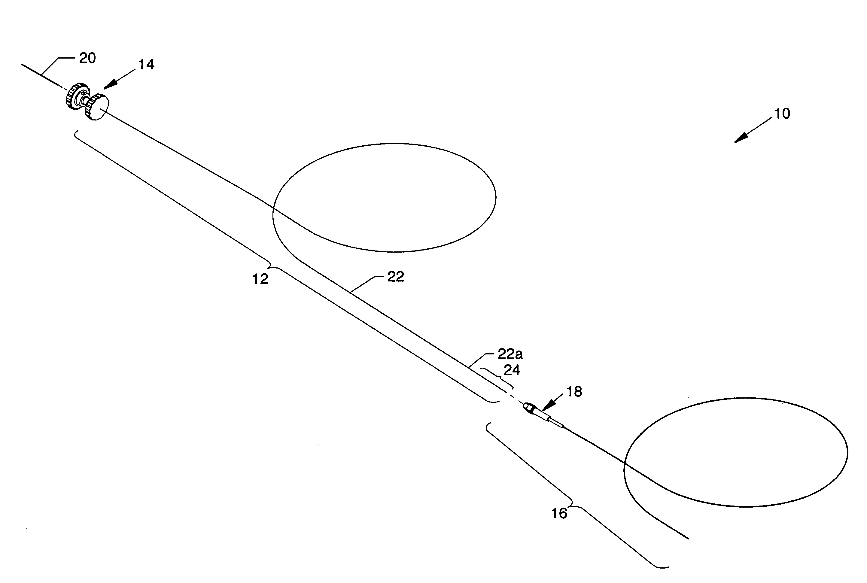
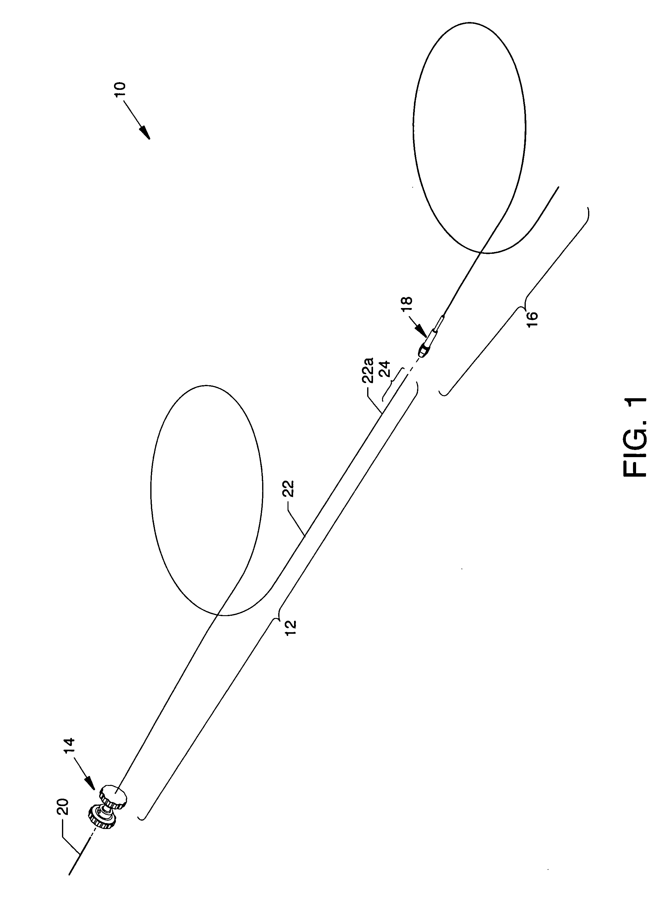
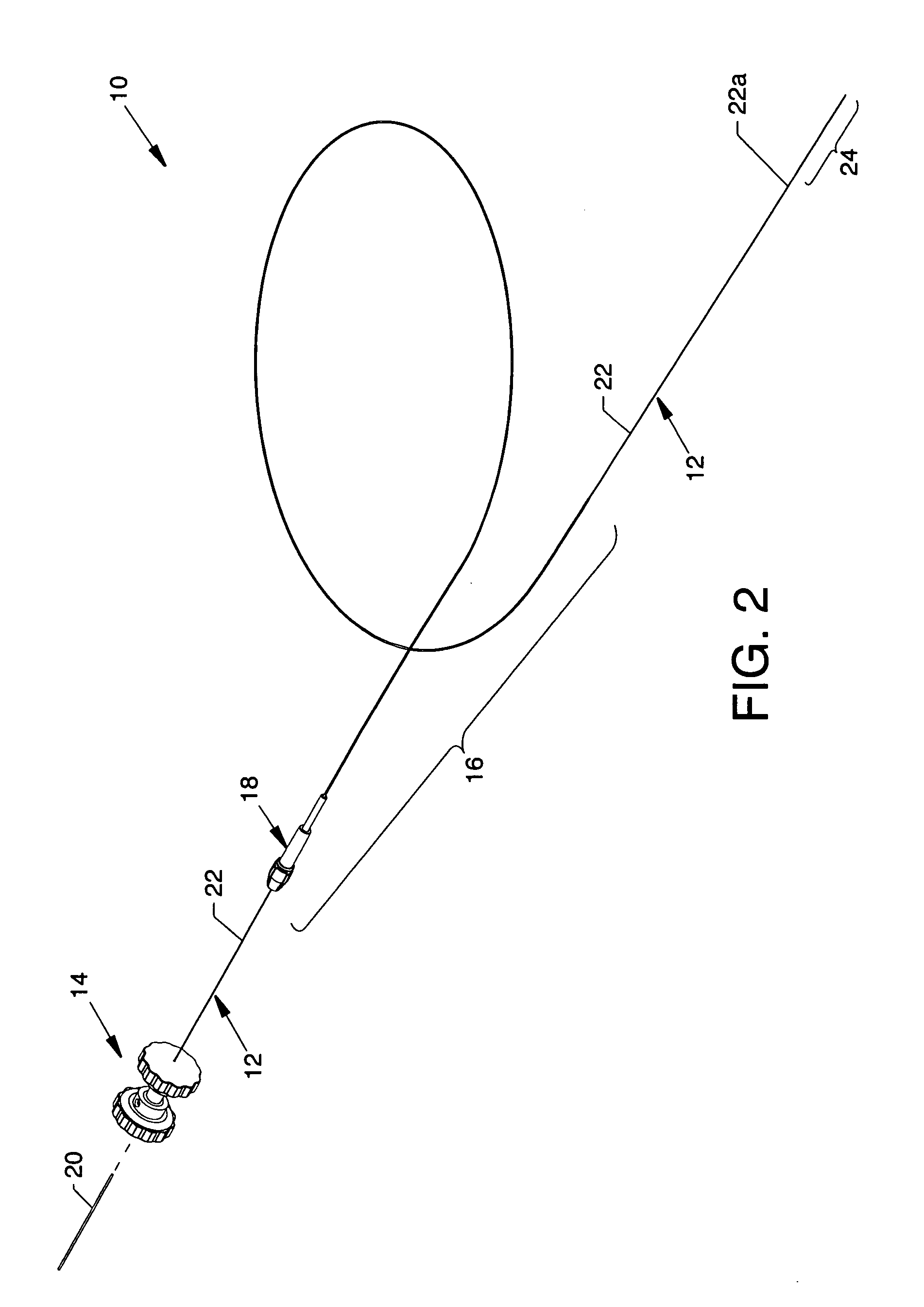
[0055]FIG. 1 is an isometric view of the infusion flow guidewire system 10 wherein the major components are shown separated. FIG. 2 is an isometric view of the components of the infusion flow guidewire system 10 in the engaged form. Each figure illustrates readily visible components including: a flexible infusion flow guidewire 12 having a coupling assembly 14 removably attached at the proximal end thereof and a flexible delivery sheath 16 (also known as a guide catheter) of braided polyimide preferably having an outside diameter of 0.035 inch and an inner diameter of 0.017 inch. A proximally located torque handle 18 is shown attached to the proximal end of the delivery sheath 16. Special attention is paid to the connecting structure in the form of a high pressure supply line 20 which enables connection between an AngioJet® pump set (or another suitable device) and the infusion flow guidewire 12 where the high pressure supply line 20 does not exceed an infusion flow guidewire 12 hav...


PUM


Abstract

An infusion flow guidewire system including a delivery sheath and an infusion flow guidewire. The minimal cross section flexible infusion flow guidewire includes a nitinol hypotube, a flexible tip and distally located rearwardly directed orifices for infusion of fibrinolytics and for introduction of high pressure fluids for maceration and rearwardly directed flow of thrombus debris located in tortuous small sized vessels. Apparatus, some of which is removably attachable, is provided for grasping members of the invention for rotational torquing and for longitudinal actuation along and within the vasculature.

Description

CROSS REFERENCES TO RELATED APPLICATIONS[0001]This patent application is related to patent application Ser. No. 11 / 702,990 filed Feb. 6, 2007, entitled “Miniature Flexible Thrombectomy Catheter,” which is pending; to patent application Ser. No. 11 / 702,995 filed Feb. 6, 2007, also entitled “Miniature Flexible Thrombectomy Catheter,” which is pending; to patent application Ser. No. 11 / 237,558 filed Sep. 28, 2005, entitled “Thrombectomy Catheter Deployment System,” which is pending; and to patent application Ser. No. 11 / 581,613 filed Oct. 16, 2006, entitled “Occlusive Guidewire System Having an Ergonomic Handheld Control Mechanism Prepackaged in a Pressurized Gaseous Environment and a Compatible Prepackaged Torqueable Kink-Resistant Guidewire with Distal Occlusive Balloon,” which is pending.[0002]This application claims priority from the earlier filed U.S. Provisional Application No. 60 / 934,281 filed Jun. 12, 2007, entitled “Floppy Flow Wire”, and is hereby incorporated into this appli...

Claims


Application Information

Patent Timeline
Patent Type & Authority Applications(United States)
IPC IPC(8): A61B17/22
CPCA61B17/32037A61B2017/22038A61B2017/22049A61M2025/09083
Inventor RILES, JOHN C.BALL, DOUGLAS J.BONNETTE, MICHAEL J.THOR, ERIC J.TESCHENDORF, JOHN L.LE, HIEU V.
Owner BOSTON SCI LTD
Why Eureka
Try Eureka