Determining Density Contrast at Subsurface Interface

a density contrast and subsurface technology, applied in the direction of instruments, specific gravity measurement, material analysis, etc., can solve the problem that the process has not been too successful

Inactive Publication Date: 2008-12-18
WESTERNGECO LLC
View PDF5 Cites 7 Cited by
  • Summary
  • Abstract
  • Description
  • Claims
  • Application Information

AI Technical Summary

Benefits of technology

[0009]The above referenced summary section is provided to introduce a selection of concepts in a simplified form that are further described below in the detailed description section. The summary is not intended to identify key features or essential features of the claimed subject matter, nor is it intended to be used to limit the scope of the claimed subject matter. Furthermore, the claimed subject matter is not limited to implementations that solve any or all disadvantages noted in any part of this disclosure.

Problems solved by technology

Acoustic impedance may be successfully determined from PP inversion; however, that is not the case with density.
However, these processes have not been too successful due to technical difficulties involving PP / PS event registration, relative noisy gather of PS seismic data and the like.

Method used


Image

  • Determining Density Contrast at Subsurface Interface
  • Determining Density Contrast at Subsurface Interface
  • Determining Density Contrast at Subsurface Interface

Examples


Embodiment Construction

[0018]The discussion below is directed to certain specific implementations. It is to be understood that the discussion below is only for the purpose of enabling a person with ordinary skill in the art to make and use any subject matter defined now or later by the patent “claims” found in any issued patent herein.

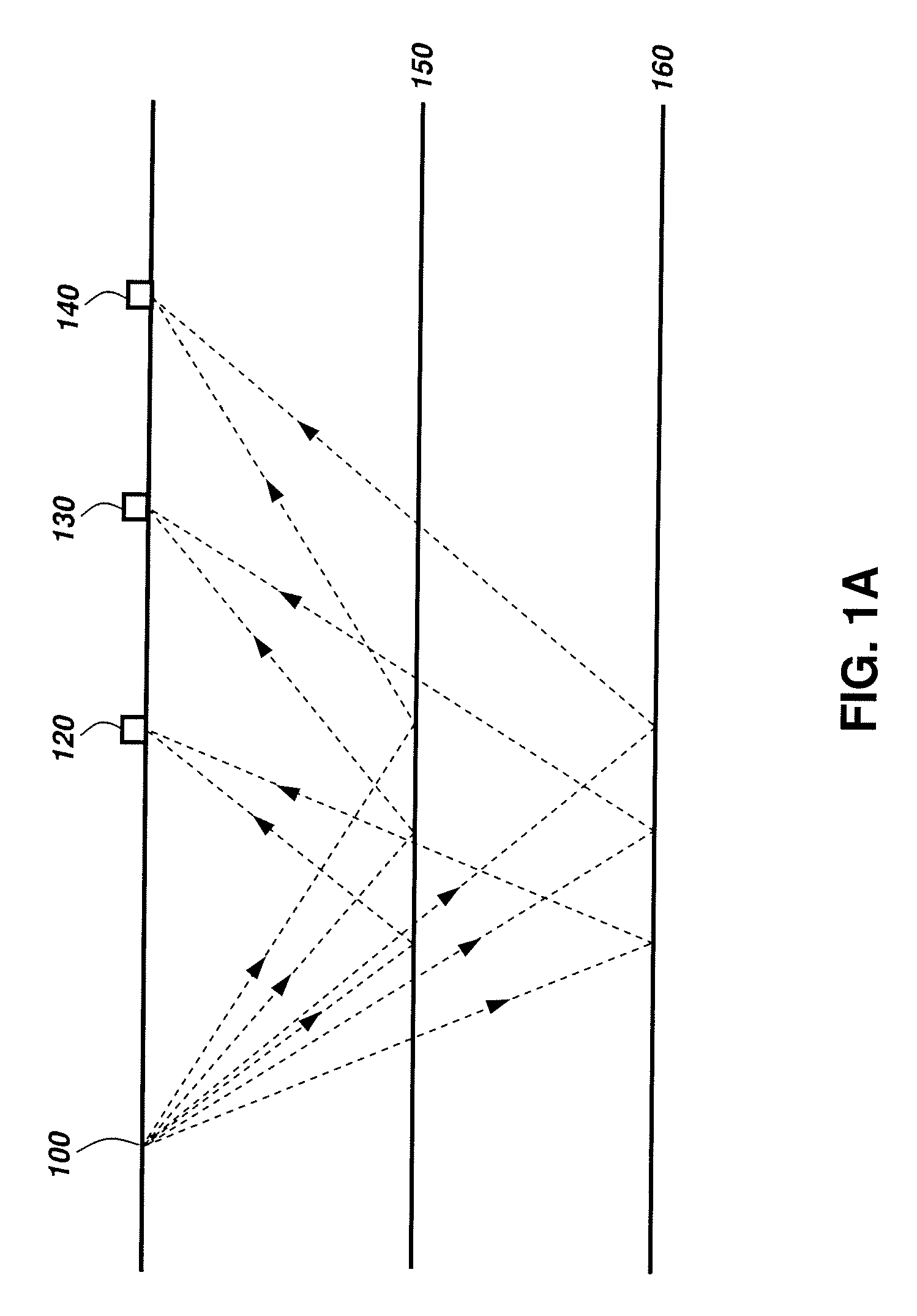
[0019]FIG. 1A illustrates a schematic diagram of a seismic survey that may be used in connection with implementations of various techniques described herein. A seismic survey is generally performed using at least one seismic source 100 and an array of seismic receivers 120, 130 and 140. For land seismic surveying, the seismic source 100 may be buried beneath the earth's surface and the seismic receivers 120, 130 and 140 may be disposed on the earth's surface. For marine seismic surveying, the seismic source 100 may be disposed below the sea water level and the seismic receivers 120, 130 and 140 may be disposed on the sea floor. When the source 100 is actuated, acoustic (or s...


PUM

PropertyMeasurementUnit
velocityaaaaaaaaaa
wave reflection coefficientaaaaaaaaaa
densityaaaaaaaaaa

Abstract

Method for subsurface exploration. In one implementation, the method may include receiving a gamma value at a subsurface interface, wherein the gamma value is a ratio of Vp/Vs at the subsurface interface. Vp is the average P wave velocity and Vs is the average S wave velocity. The method may further include receiving a converted wave reflection coefficient at the subsurface interface. The converted wave reflection coefficient is a function of a density contrast at the subsurface interface and a shear velocity contrast at the subsurface interface. The method may further include determining a P wave incident angle such that the converted wave reflection coefficient is a function of substantially only the density contrast at the P wave incident angle. The P wave incident angle is referred to herein as θ. The method may further include calculating the density contrast based on the converted wave reflection coefficient at θ.

Description

BACKGROUND[0001]1. Field of the Invention[0002]Implementations of various technologies described herein generally relate to density contrast determination at the subsurface interface.[0003]2. Description of the Related Art[0004]The following descriptions and examples do not constitute an admission as prior art by virtue of their inclusion within this section.[0005]It is common knowledge in oil and gas industry that density is the key element in distinguishing commercial gas from fizz. Acoustic impedance may be successfully determined from PP inversion; however, that is not the case with density.[0006]Some efforts have been made in using multicomponent seismic data to obtain density information. In particular, PP / PS joint inversion and PS inversion have been used to obtain density information from multicomponent seismic data. However, these processes have not been too successful due to technical difficulties involving PP / PS event registration, relative noisy gather of PS seismic data...

Claims


Application Information

Patent Timeline
Patent Type & Authority Applications(United States)
IPC IPC(8): G01N9/36
CPCG01N9/24G01V1/30
Inventor ZOU, KESHAN
Owner WESTERNGECO LLC
Why Eureka
Try Eureka