
Vehicle side door structure

Inactive Publication Date: 2008-12-25
TOYOTA JIDOSHA KK
View PDF7 Cites 25 Cited by
  • Summary
  • Abstract
  • Description
  • Claims
  • Application Information

AI Technical Summary

Benefits of technology

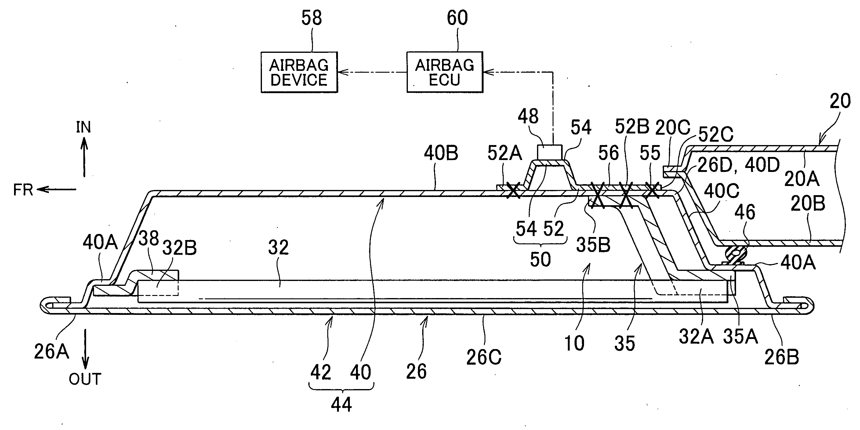
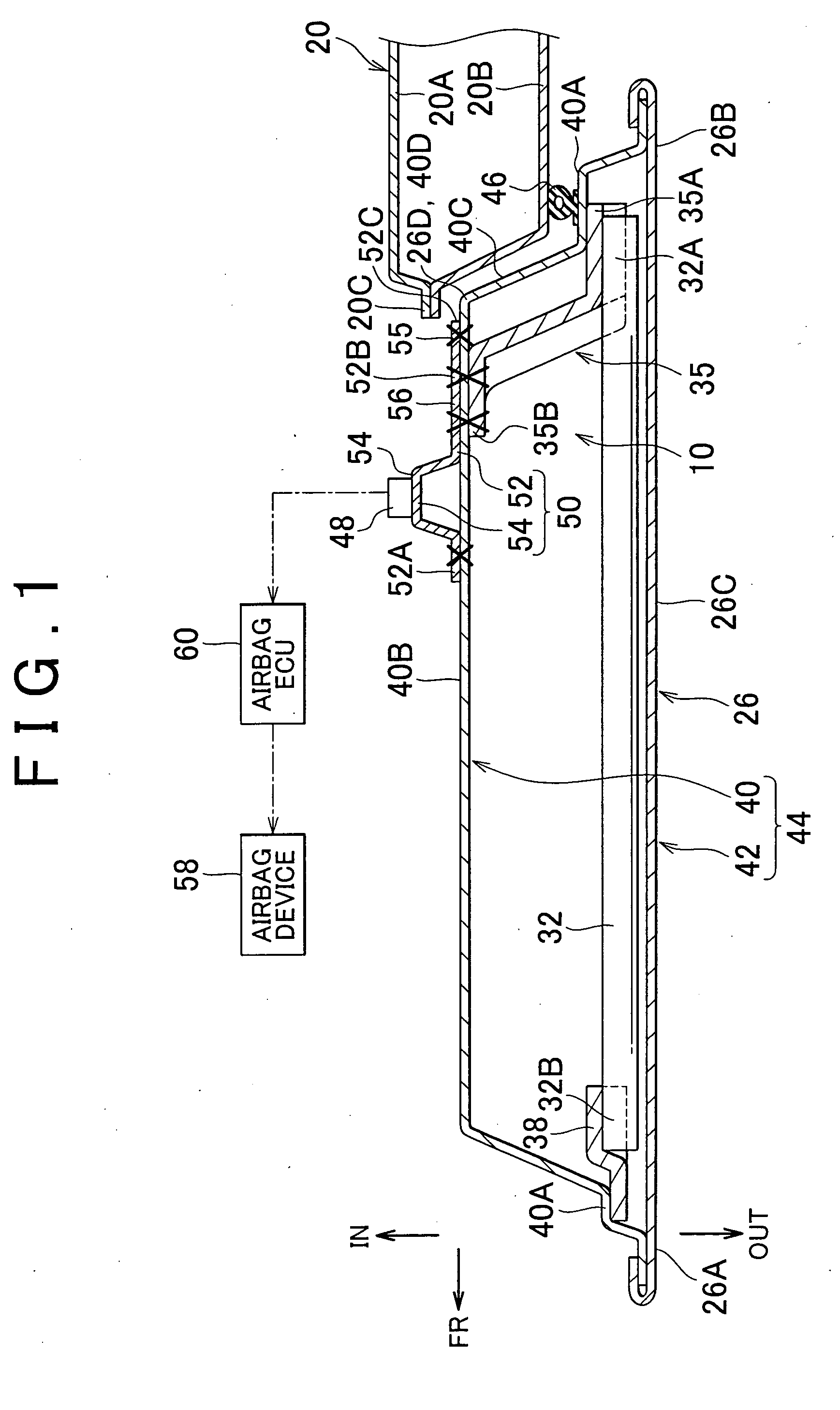
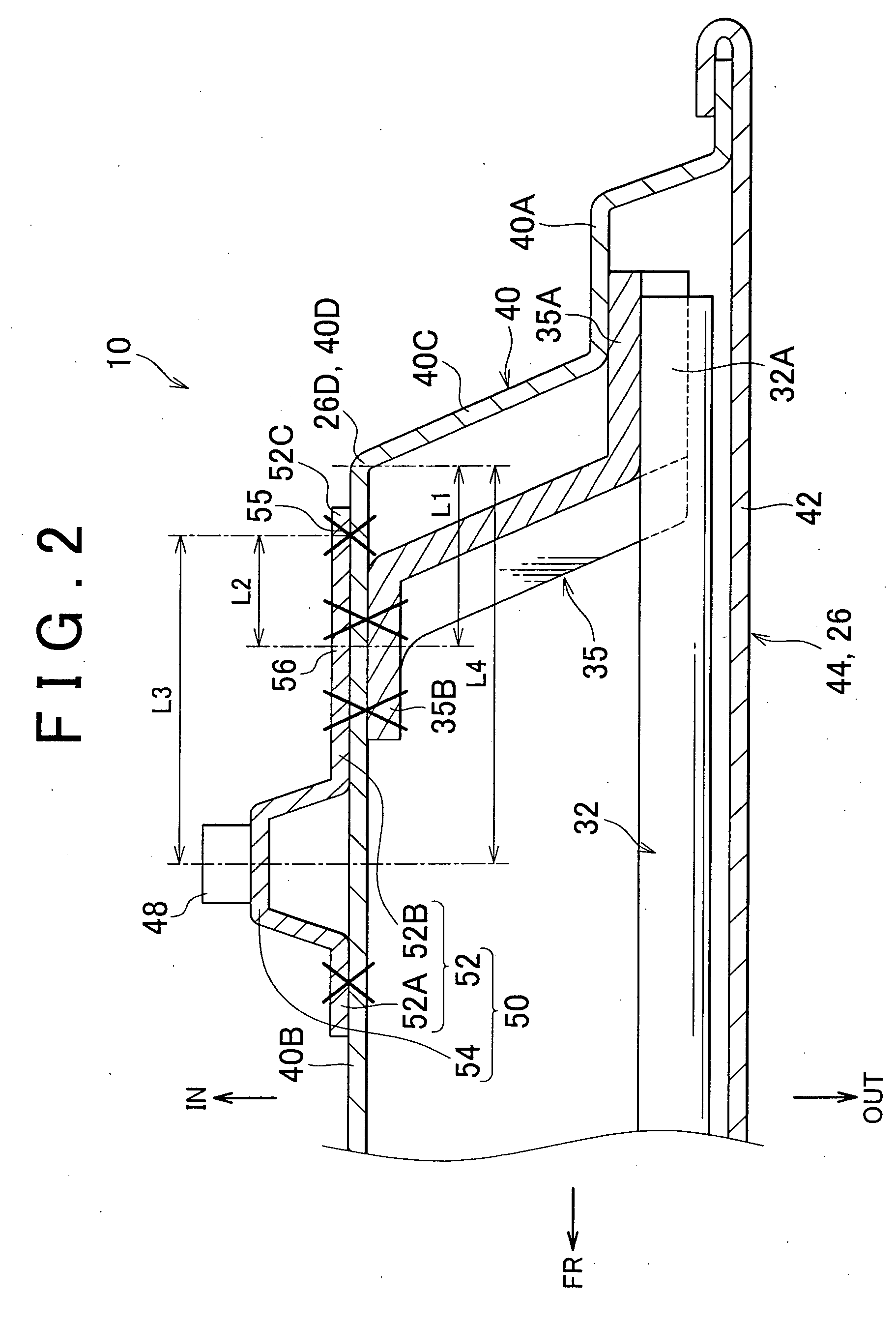
[0009]With the vehicle side door structure according to the aspect of the invention described above, for example, when a collision load is locally applied to a portion of the impact beam, the collision load is transmitted to the inner panel via the load transmission member. In the vehicle side door structure, the bracket that holds the collision detector is arranged in such a manner that the bracket overlaps a portion of the inner panel, to which the load transmission member is connected, from a lateral view. In other words, at least a portion of the bracket overlaps the portion of the inner panel, to which the load transmission member is connected, in the longitudinal direction of the vehicle body and in the vehicle-height direction. Therefore, the load (e.g., acceleration or displacement) is efficiently transmitted from the load transmission member to the collision detector via the bracket.
[0016]With this structure, for example, when a collision load which is equal to or higher than the predetermined value is locally applied to a portion of the impact beam, the rear end portion (portion near the rear end portion) of the inner panel contacts the vehicle body structural portion. Therefore, a pivot motion of the bracket about the portion (fulcrum) of the bracket which is connected to the inner panel is easily caused. Accordingly, with this vehicle side door structure, the bracket serves as a lever more effectively. Therefore, more significantly amplified load (e.g., acceleration or displacement) is transmitted to the collision detector. If the structure is employed in which the portion of the bracket which is fixedly connected to the inner panel contacts the vehicle body structural portion, further significantly amplified load is applied to the collision detector.
[0020]In the vehicle side door structure described above, the load transmission member is connected to, and the bracket is fitted to, the substantially flat plate portion of the inner panel. Therefore, it is possible to flexibly set the position (e.g., the point of load application described above) in the bracket, at which the load is transmitted from the load transmission member to the bracket. Therefore, the load that is to be applied to the collision detector (amplification ratio) is adjusted easily on an as-required basis.
[0022]The vehicle side door structure according to the aspect of the invention described above has an excellent effect of amplifying a load that is to be applied to the collision detector when the load is locally applied to the side door.

Problems solved by technology

However, the above-described technology has a problem that, if a load is locally applied to the side door at a portion distant from the accelerometer, the value indicated by a signal from the accelerometer does not rise sufficiently quickly.
Therefore, the force with which the collision detector is restrained by the inner panel is weak.

Method used


Image

  • Vehicle side door structure
  • Vehicle side door structure
  • Vehicle side door structure

Examples


Embodiment Construction

[0030]Hereafter, a vehicle side door structure 10 according to a first embodiment of the invention will be described with reference to FIGS. 1 to 4. An arrow FR, an arrow UP, an arrow IN and an arrow OUT respectively indicate the forward direction (traveling direction), the upward direction, the vehicle-width inward direction, and the vehicle-width outward direction of an automobile to which the vehicle side door structure 10 is applied.

[0031]FIG. 4 is a side view showing an automobile A to which the vehicle side door structure 10 is applied. As shown in FIG. 4, the automobile A has a front vehicle body opening 12 and a rear vehicle body opening 14 through which a passenger gets on and off the automobile A. The vehicle body openings 12 and 14 are formed in a side portion of a vehicle body. More specifically, the front vehicle body opening 12 is defined by a front pillar 16, a roof side-rail 18, a center pillar 20, and a rocker 22 that constitute a vehicle body frame. Similarly, the ...


PUM


Abstract

A vehicle side door structure includes an inner panel, an outer panel that is positioned on the outside of the inner panel in the vehicle-width direction, and that forms a closed space in cooperation with the inner panel. In addition, an impact beam extends in the longitudinal direction of a vehicle body, and is arranged within the closed space at a position close to the outer panel, a bracket is attached to the inner panel and holds, at a portion which is on the inner side of the inner panel in the vehicle-width direction, a collision detector, and a load transmission member connects the impact beam to the inner panel at a portion that overlaps the bracket from a lateral view.

Description

INCORPORATION BY REFERENCE[0001]The disclosure of Japanese, Patent Application No. 2007-164789 filed on Jun. 22, 2007 including the specification, drawings and abstract is incorporated herein by reference in its entirety.BACKGROUND[0002]1. Field of the Invention[0003]The invention relates to a vehicle side door structure that is applied to vehicles such as automobiles.[0004]2. Description of Related Art[0005]For example, Japanese Patent Application Publication No. 07-2049 (JP-A-07-2049) describes a technology of fitting an accelerometer to an inner panel of a side door via a supporting member made of a plate metal. The accelerometer outputs a signal based on which a determination is made as to whether an airbag housed in the side door should be deployed.SUMMARY[0006]However, the above-described technology has a problem that, if a load is locally applied to the side door at a portion distant from the accelerometer, the value indicated by a signal from the accelerometer does not rise ...

Claims


Application Information

Patent Timeline
IPC IPC(8): B62D25/02
CPCB60J5/0437
Inventor OKA, YUKIO
Owner TOYOTA JIDOSHA KK
Learn More