Load drive control circuit

a technology of load drive and control circuit, which is applied in the direction of dynamo-electric converter control, dc motor rotation control, pulse technique, etc., can solve problems such as damage to activated transistors, and achieve the effect of preventing erroneous load operation

Inactive Publication Date: 2008-12-25
KK TOKAI RIKA DENKI SEISAKUSHO
View PDF8 Cites 26 Cited by
  • Summary
  • Abstract
  • Description
  • Claims
  • Application Information

AI Technical Summary

Benefits of technology

[0012]In such a structure, each bridge circuit is in a low state when operation of the load is suspended. When the detection circuit detects the occurrence of a higher potential point short circuit at the first terminal or second terminal of the load when operation of the load is suspended, the control circuit switches each bridge circuit from a low state to a high impedance state and electrically disconnects the load from the power supply. Thus, even if a higher potential point short circuit occurs at the first terminal of the load, overcurrent will not flow into the semiconductor elements of the bridge circuit since the bridge circuits are in the high-impedance sta...

Problems solved by technology

This may damage t...

Method used


Image

  • Load drive control circuit
  • Load drive control circuit
  • Load drive control circuit

Examples


Embodiment Construction

[0026]A load drive control circuit according to a preferred embodiment of the present invention will now be discussed with reference to FIGS. 1 to 5.

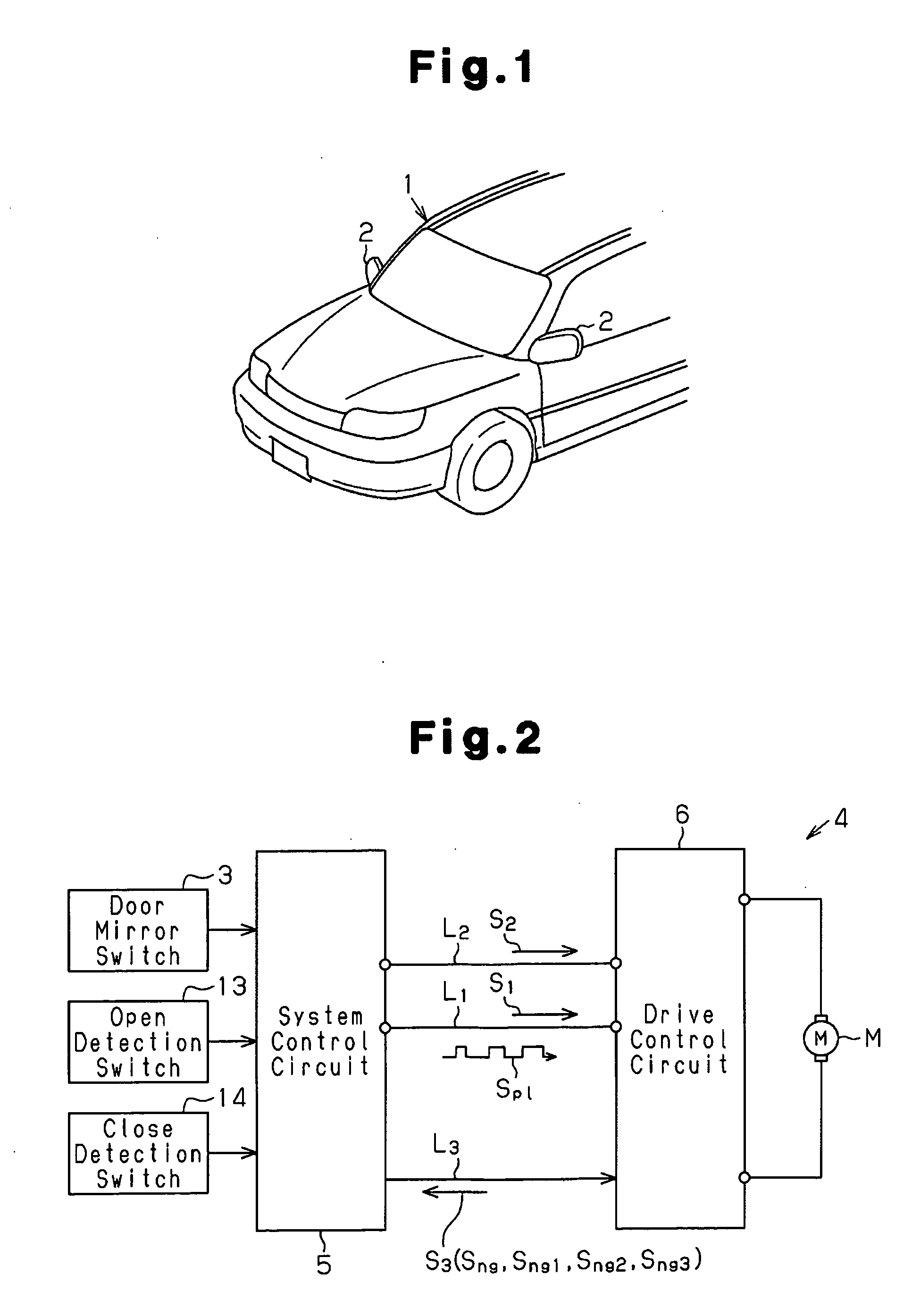
[0027]As shown in FIG. 1, a vehicle 1 includes door mirrors (sideview mirrors) 2 arranged on the front doors. Each door mirror 2 folds, or opens and closes, when driven by a drive source such as a motor M (see FIG. 2). A door mirror switch 3 (see FIG. 2), which is arranged in the passenger compartment, is operated to open and close the door mirrors 2. For example, when the door mirrors 2 are in an open state, if the door mirror switch 3 is operated to fold or open the door mirrors 2, each door mirror 2 is turned toward the vehicle body and folded. When the door mirror 2 is in a folded state, if the door mirror switch 3 is operated to open or unfold the door mirrors 2, each door mirror 2 is turned away from the vehicle body and returned to the open state. The operations for opening and closing the door mirrors 2 may be performed under co...


PUM


Abstract

A load drive control circuit for controlling a load that includes connection terminals. The load drive control circuit includes bridge circuits respectively connected to the connection terminals of the load. Each bridge circuit includes two semiconductor elements, which are connected between a power supply and ground, and an output terminal. The semiconductor elements are each controlled to be switched between activated and deactivated states. The output terminal of each bridge circuit generates a bridge output that varies in accordance with a combination of the activated and deactivated states of the semiconductor elements in the bridge circuit. A detection circuit detects whether a short circuit is occurring in the connection terminals. A control circuit switches the bridge circuits to electrically disconnect the load from the power supply when a short circuit is occurring during a period in which the load is in a suspended state.

Description

BACKGROUND OF THE INVENTION[0001]The present invention relates to a load drive control circuit for controlling the driving of a load such as a motor, a lamp, or the like.[0002]In the prior art, a motor driver, such as a motor drive circuit, is used for driving a motor. Patent document 1 describes an H-bridge type motor drive circuit. FIG. 6 shows an H-bridge type motor drive circuit 81. The motor drive circuit 81 includes a first bridge circuit 83, which is connected to a first terminal M1 of a motor 82, and a second bridge circuit 84, which is connected to a second terminal M2 of the motor 82. The first bridge circuit 83 includes two series-connected transistors 85 and 86 connected in series. A node or an output terminal between the transistors 85 and 86 is connected to the first terminal M1 of the motor 82. The second bridge circuit 84 also includes two series-connected transistors 87 and 88. A node or an output terminal between the transistors 87 and 88 is connected to the second...

Claims


Application Information

Patent Timeline
IPC IPC(8): H02P7/00H02H3/00H02P3/06H02P7/29H02P7/291
CPCB60R1/074H03K17/0822H03K17/6872H03K2217/0045H02P7/04
Inventor NISHIBE, YASUSHIKISHI, HIROKI
Owner KK TOKAI RIKA DENKI SEISAKUSHO
Why Eureka
Try Eureka