Key Control Circuit, Electronic Apparatus, Portable Device, and Key Control Method

a key control circuit and key control technology, applied in the field of key control, can solve the problems of unintended key pressing, portable terminal devices may also be subjected to additional pressure load, and are likely to be under pressure, so as to reduce power consumption in key searching

Inactive Publication Date: 2008-12-25
FUJITSU LTD
View PDF7 Cites 31 Cited by
  • Summary
  • Abstract
  • Description
  • Claims
  • Application Information

AI Technical Summary

Benefits of technology

[0023]An object of the present invention relates to key control on a key matrix circuit having a plurality of keys, and is to reduce power consumption in key searching that is caused by unintended key pressing.

Problems solved by technology

The portable terminal device is put in a bag or a pocket of a garment to be carried around, and is likely to be under pressure load when carried around.
Aside from natural load that arises when portable terminal device is carried, the portable terminal device may also be subjected to additional pressure load that is caused by a user's attaching a “peeking preventive sheet” or “key top face seal”.
An openable / closable portable device poses a problem when its housing becomes thinner and a so-called clearanceless effort progresses to reduce a gap between a fixed side housing unit and a movable side housing unit.
The problem is that foreign matter may come in between the fixed side housing and the movable side housing to cause an unintended key pressing.
The occurrence of key pressing leads to key pressing detection, which consumes unnecessary currents.
This current consumption accelerates the exhaustion of a battery.
This approach allows masking of only the internal keys, but complicates the circuit structure and doubles the burden of a key searching function.
The approach, therefore, is not recommendable.
When any one of the internal keys allowing pressing detection is pressed, therefore, the pressing detection as described above is carried out, which results in unnecessary power consumption.
About these problems, Japanese Patent Application Laid-Open Publication Nos. 2006-4052, H09-64803, and 2004-128814 do not disclose or suggest anything, and do not disclose any solution to the problems, either.

Method used


Image

  • Key Control Circuit, Electronic Apparatus, Portable Device, and Key Control Method
  • Key Control Circuit, Electronic Apparatus, Portable Device, and Key Control Method
  • Key Control Circuit, Electronic Apparatus, Portable Device, and Key Control Method

Examples


first embodiment

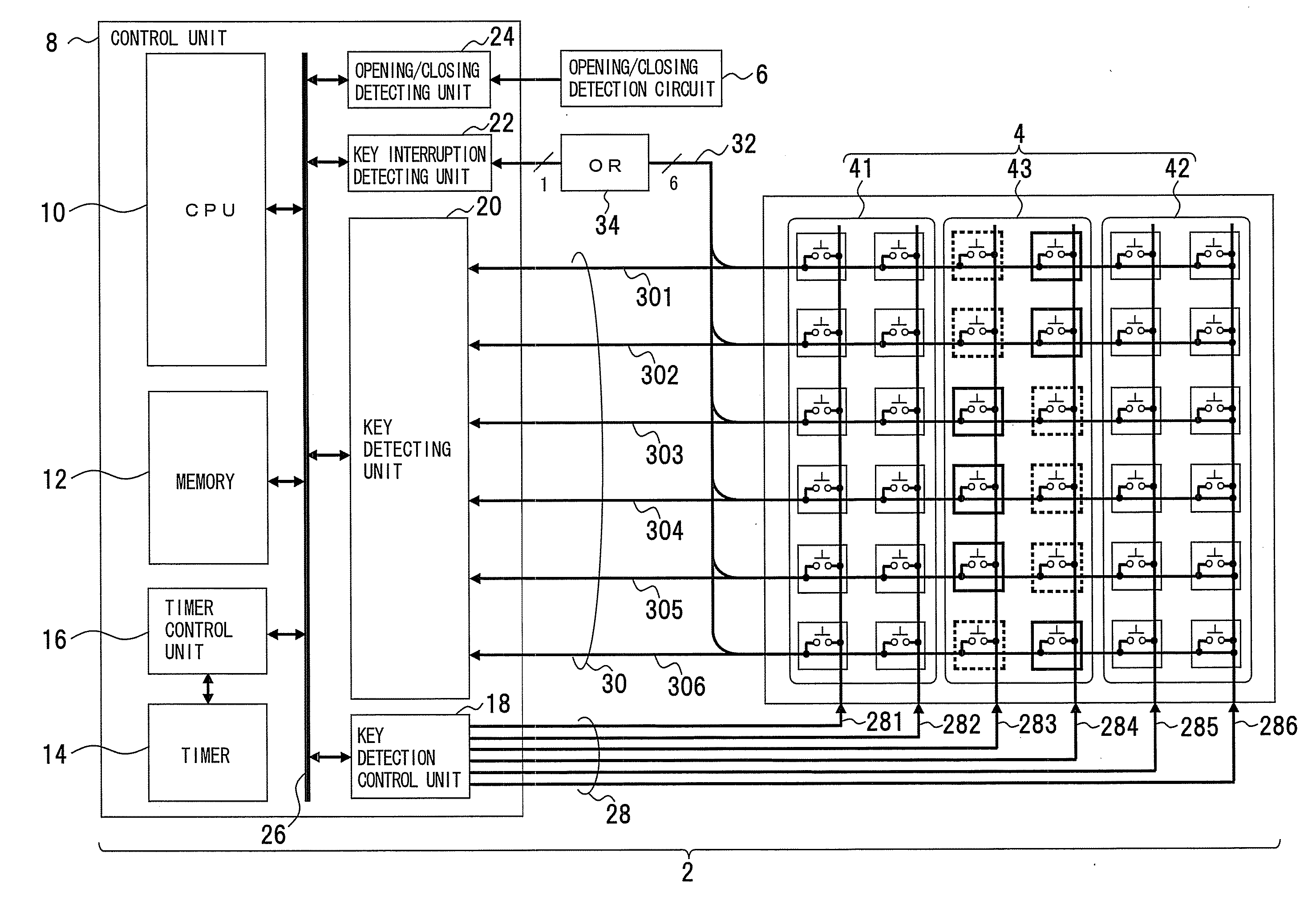
[0076]FIGS. 4, 5, 6, and 7 will be referred to in describing a first embodiment of the present invention. FIG. 4 depicts an example of the configuration of a portable device of a first embodiment, FIG. 5 depicts an enlarged view of a key matrix circuit, FIG. 6 depicts an example of the configuration of a key detection control unit, and FIG. 7 depicts an example of the configuration of a key detecting unit.

[0077]The portable device 2 is an embodiment of a key control circuit, an electronic apparatus, a portable device, and a key control method of the present invention, and is provided in the form of, for example, a cellular phone that is equipped with a computer to offer a communication function and an information processing function. The portable device 2 includes a key matrix circuit 4, an opening / closing detection circuit 6, and a control unit 8.

[0078]The key matrix circuit 4 is a switch circuit that is composed of a plurality of rows and columns of keys in matrix arrangement and ...

second embodiment

[0126]FIG. 16 will then be referred to in describing a second embodiment of the present invention. FIG. 16 depicts an example of a key control circuit of the second embodiment. In FIG. 16, the same constituent elements as described in FIG. 4 are denoted by the same reference numerals.

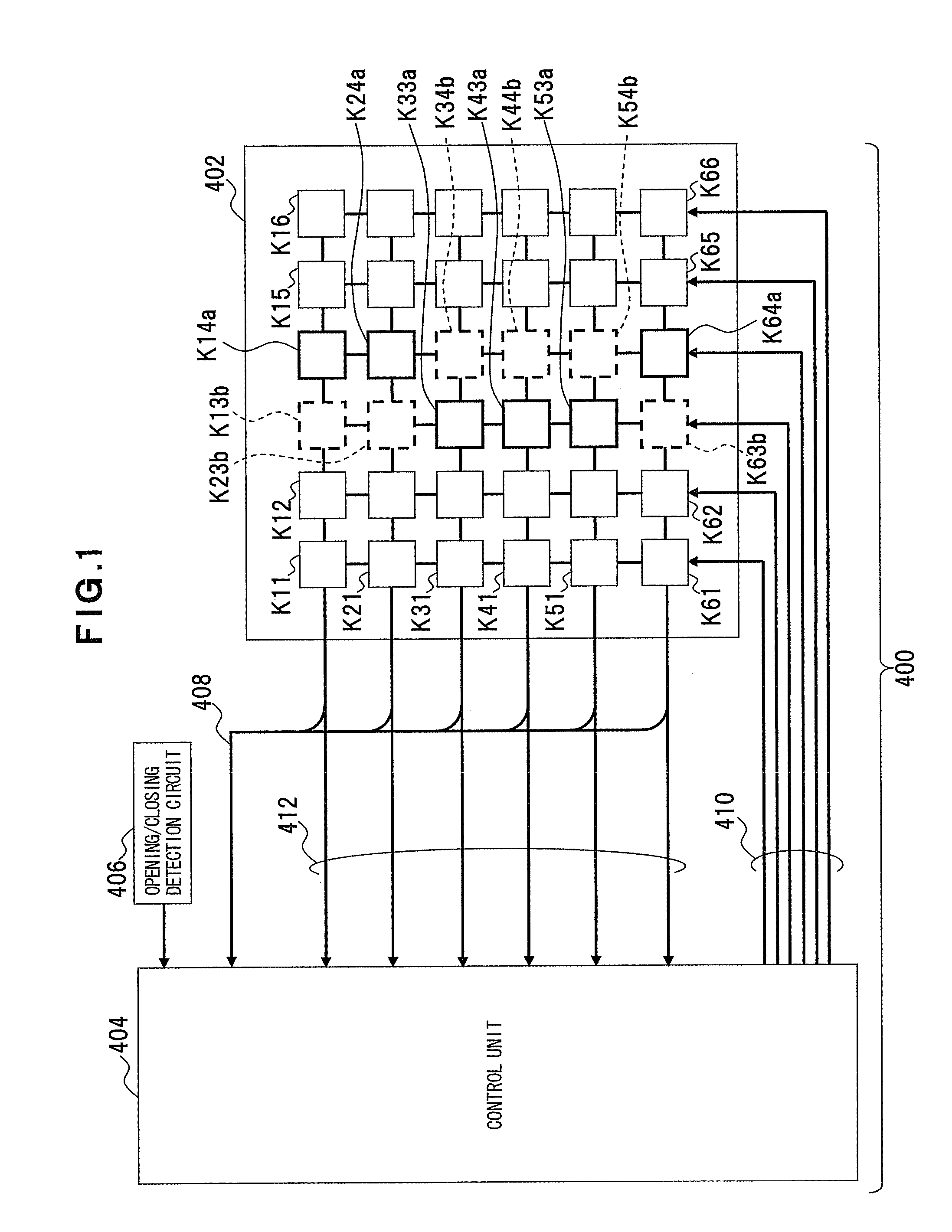
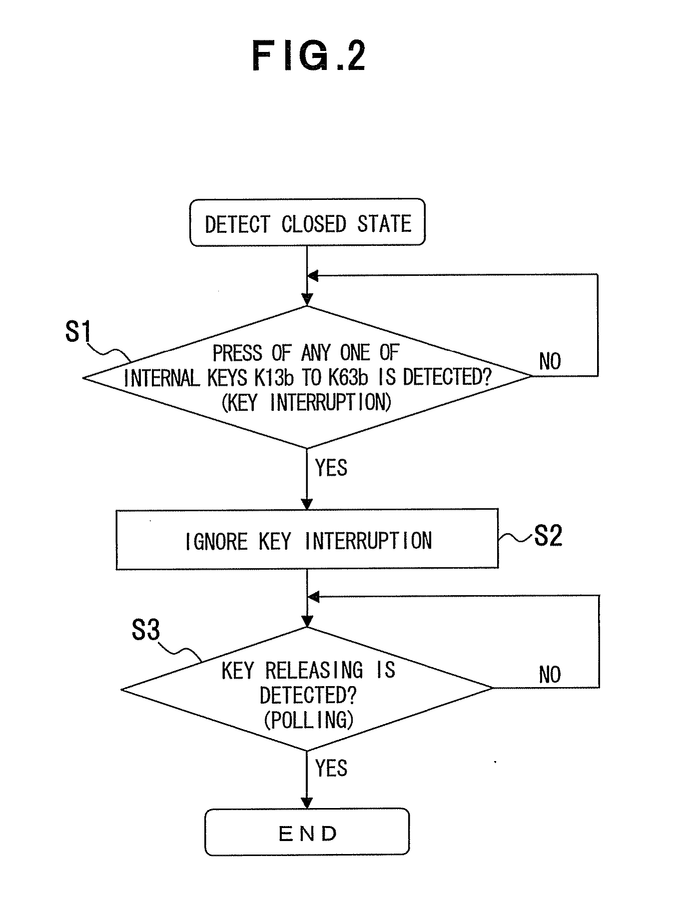
[0127]In the first embodiment, when the portable device 2 is in the closed state, the key pressing function of keys in the key groups 41 and 42 is masked as key pressing detection is made possible for the key switches K14a, K24a, K33a, K43a, K53a, and K64a, which are the external keys belonging to the key group 43, and the key switches K13b, K23b, K34b, K44b, K54b, and K63b, which are the internal keys belonging to the key group 43. Thus, polling is executed in response to an event of pressing of any one of the key switches K13b, K23b, K34b, K44b, K54b, and K63b belonging to the key group 43, and key pressing is detected at regular intervals.

[0128]In the second embodiment, any one of or all of key group...


PUM


Abstract

Key control for a key matrix circuit having a plurality of keys is provided to reduce power consumption in key searching caused by unintended key pressing. In key control on the key matrix circuit having a plurality of rows and columns of keys (key switches) in matrix arrangement, keys are disabled or enabled in row lines or in column lines on the key matrix circuit by any one of the lines through key selection by a key selecting means (opening/closing detection circuit, opening/closing detecting unit, key selection switch, key selecting unit). Following key selection, a control means (control unit) keeps key pressing detection in a standby status for a predetermined time in response to an event of detection of a press of a key included in enabled keys, and resumes the key pressing detection after the passage of the predetermined time.

Description

CROSS-REFERENCE TO RELATED APPLICATIONS[0001]This application is based upon and claims the benefit of priority from the prior Japanese Patent Application No. 2007-161580, filed on Jun. 19, 2007, the entire contents of which are incorporated herein by reference.BACKGROUND OF THE INVENTION[0002]1. Field of the Invention[0003]The present invention relates generally to key control in an electronic apparatus, a portable device, etc., which have a key matrix circuit, and, more particularly, to a key control circuit, an electronic apparatus, a portable device, and a key control method that suppress current consumption resulting from unintended key pressing.[0004]2. Description of the Related Art[0005]A portable terminal device is one form of an electronic apparatus having a plurality of keys and a built-in key matrix circuit that detects pressing of any one of the keys. Such a portable terminal device has now evolved into a third generation portable device, which comes to have enlarged fun...

Claims


Application Information

Patent Timeline
Patent Type & Authority Applications(United States)
IPC IPC(8): H03K17/94H04M1/02
CPCH03M11/20G06F1/32G06F3/02H04B1/00
Inventor MINATO, KIYOMIUEYAMA, SATORU
Owner FUJITSU LTD
Why Eureka
Try Eureka