Display device

Active Publication Date: 2008-12-25
JAPAN DISPLAY INC
View PDF17 Cites 12 Cited by
  • Summary
  • Abstract
  • Description
  • Claims
  • Application Information

AI Technical Summary

Benefits of technology

[0021]The following briefly describes the effect that can be obtained from a representative example of the invention as disclosed in this application.
[0

Problems solved by technology

CMOS circuits have problems in that the number of

Method used


Image

  • Display device
  • Display device
  • Display device

Examples


Embodiment Construction

[0042]The following section describes in detail an embodiment of this invention in reference to drawings.

[0043]In all the drawings intended to describe the embodiment, items having the same function are assigned the same reference symbols, and repetitious descriptions are omitted.

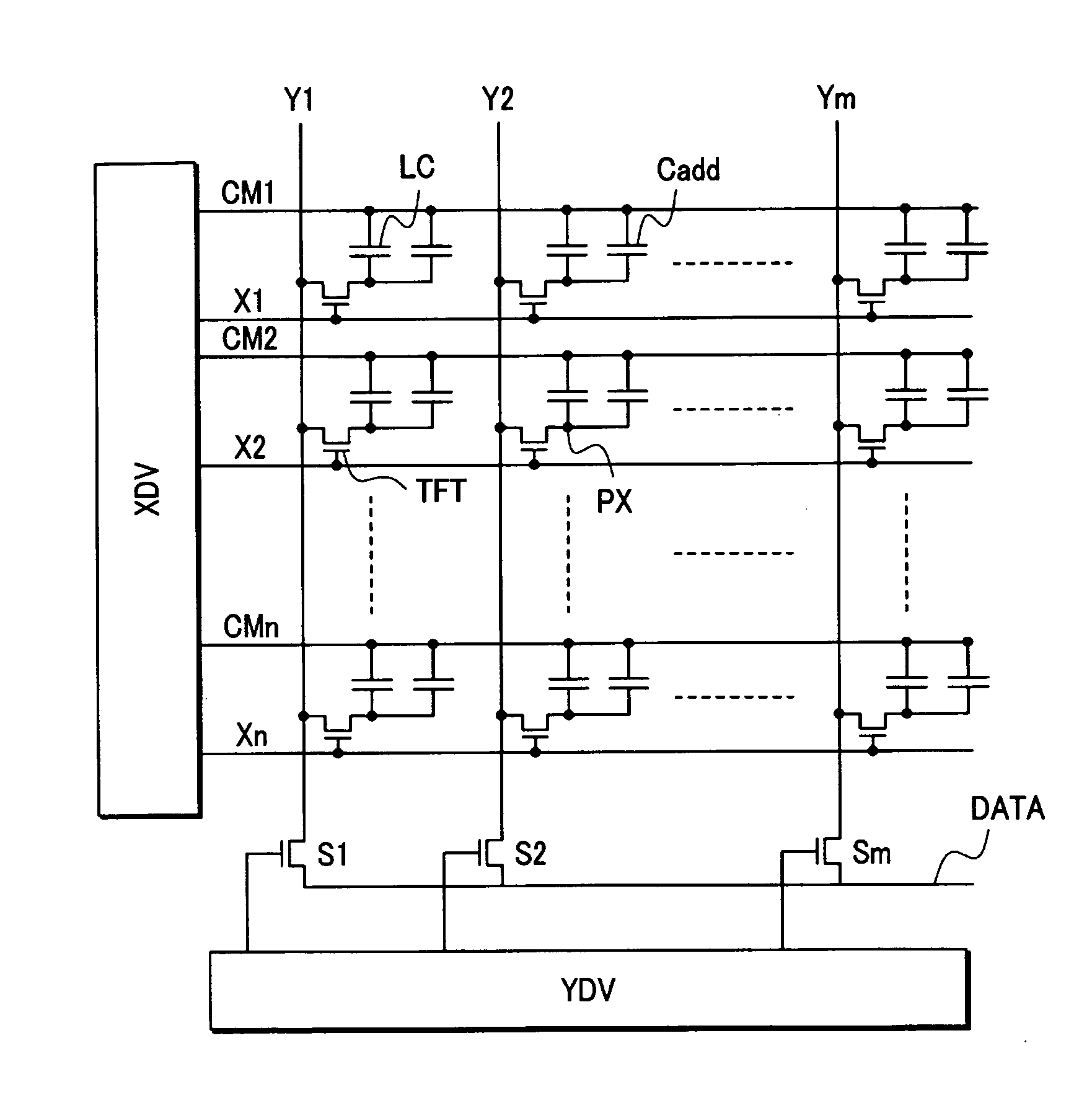
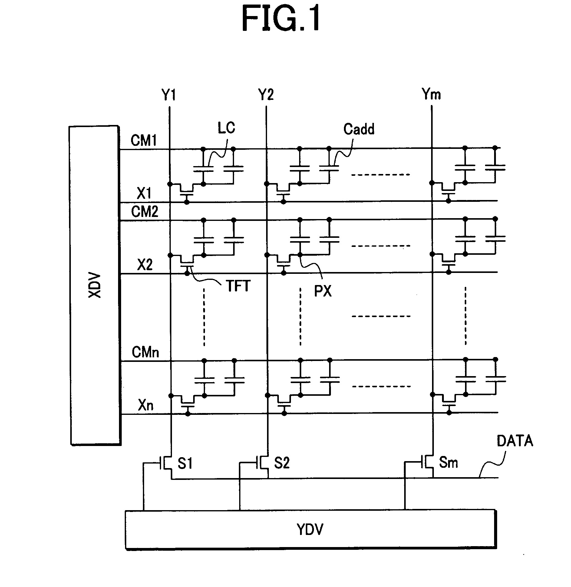
[0044]FIG. 1 is a circuit diagram showing an equivalent circuit in the active matrix liquid crystal display module in an embodiment of this invention.

[0045]As shown in FIG. 1, the active matrix liquid crystal display module in this embodiment is an active matrix liquid crystal display module using an in-plane switching (IPS) liquid crystal display panel. The module has a pair of substrates facing mutually via the liquid crystal. On the liquid crystal surface of one of the substrates, there are n gate lines (G1, G2, . . . , Gn) extending in the x direction, n common lines (also referred to as common electrodes) (CM1, CM2, . . . , CMn) extending in the x direction, and m drain lines (Y1, Y2, . . . , Ym) exten...


PUM


Abstract

A shift register circuit has a plurality of shift pulse generation circuits, and a scanning voltage generation circuit has a plurality of base circuits. The base circuits are presented with a first shift pulse generated by a shift pulse generation circuit, and a scanning line clock. The base circuits have a first transistor in which the first shift pulse is input to a first electrode, and a first power supply voltage is input to a control electrode; and a second transistor in which a control electrode is connected to a second electrode in the first transistor, a scanning line clock is input to the first electrode, and the second electrode is connected to a scanning voltage output terminal. The base circuits output a selected scanning voltage synchronized with the scanning line clock from the scanning voltage output terminal when the first shift pulse is at a first voltage level.

Description

CROSS-REFERENCE TO RELATED APPLICATION[0001]The present application claims priority from Japanese application JP2007-156054 filed on Jun. 13, 2007, the content of which is hereby incorporated by reference into this application.BACKGROUND OF THE INVENTION[0002]1. Field of the Invention[0003]The present invention relates to a display device, and in particular relates to a display device that is capable of switching between driving scan lines either simultaneously as a plurality or individually in sequence.[0004]2. Description of the Related Art[0005]Thin film transistor (TFT) liquid crystal display modules are widely used in display devices of notebook personal computers and the like. In particular, liquid crystal display modules provided with small-size liquid crystal display panels are used as display devices in portable devices such as portable telephones, for example, that are carried constantly.[0006]If a liquid crystal display panel with VGA resolution (640×3×480) is used in a l...

Claims


Application Information

Patent Timeline
IPC IPC(8): G09G3/36
CPCG09G3/3674G09G2310/0286G11C19/184
Inventor SHIGAKI, TAKUMISATO, HIDEOMAKI, MASAHIRO
Owner JAPAN DISPLAY INC
Why Eureka
Try Eureka