Liquid crystal display apparatus

a liquid crystal display and liquid crystal technology, applied in non-linear optics, instruments, optics, etc., can solve the problems of inability to maintain a inability to increase the area of light reflection film, and inability to achieve large light reflection factor, so as to improve the quality of display, without increasing the number of production steps

Inactive Publication Date: 2008-12-25
PANASONIC LIQUID CRYSTAL DISPLAY CO LTD +1
View PDF4 Cites 6 Cited by
  • Summary
  • Abstract
  • Description
  • Claims
  • Application Information

AI Technical Summary

Benefits of technology

[0023]The liquid crystal display apparatus constructed as above can improve the quality of display in the light reflection domain without increasing the number of production steps.

Problems solved by technology

In this case, even with an insulator film is formed to cover the light reflection film, the ruggedness on the light reflection film reflects on the surface of the insulator film, with the result that the thickness of a layer of liquid crystals becomes irregular in the light reflection domain, giving rise to inexpedience of degrading the contrast.
Further, when the light reflection film will sometimes be formed in flush with, for example, a signal bus line for the purpose of reducing the number of production steps but the light reflection film is physically separated from the signal bus line to keep stray capacitance from being set up between adjacent pixel electrodes, thus raising a disadvantage that the area of the light reflection film cannot be increased, failing to maintain a large light reflection factor.

Method used


Image

  • Liquid crystal display apparatus
  • Liquid crystal display apparatus
  • Liquid crystal display apparatus

Examples


embodiment 1

(Equivalent Circuit)

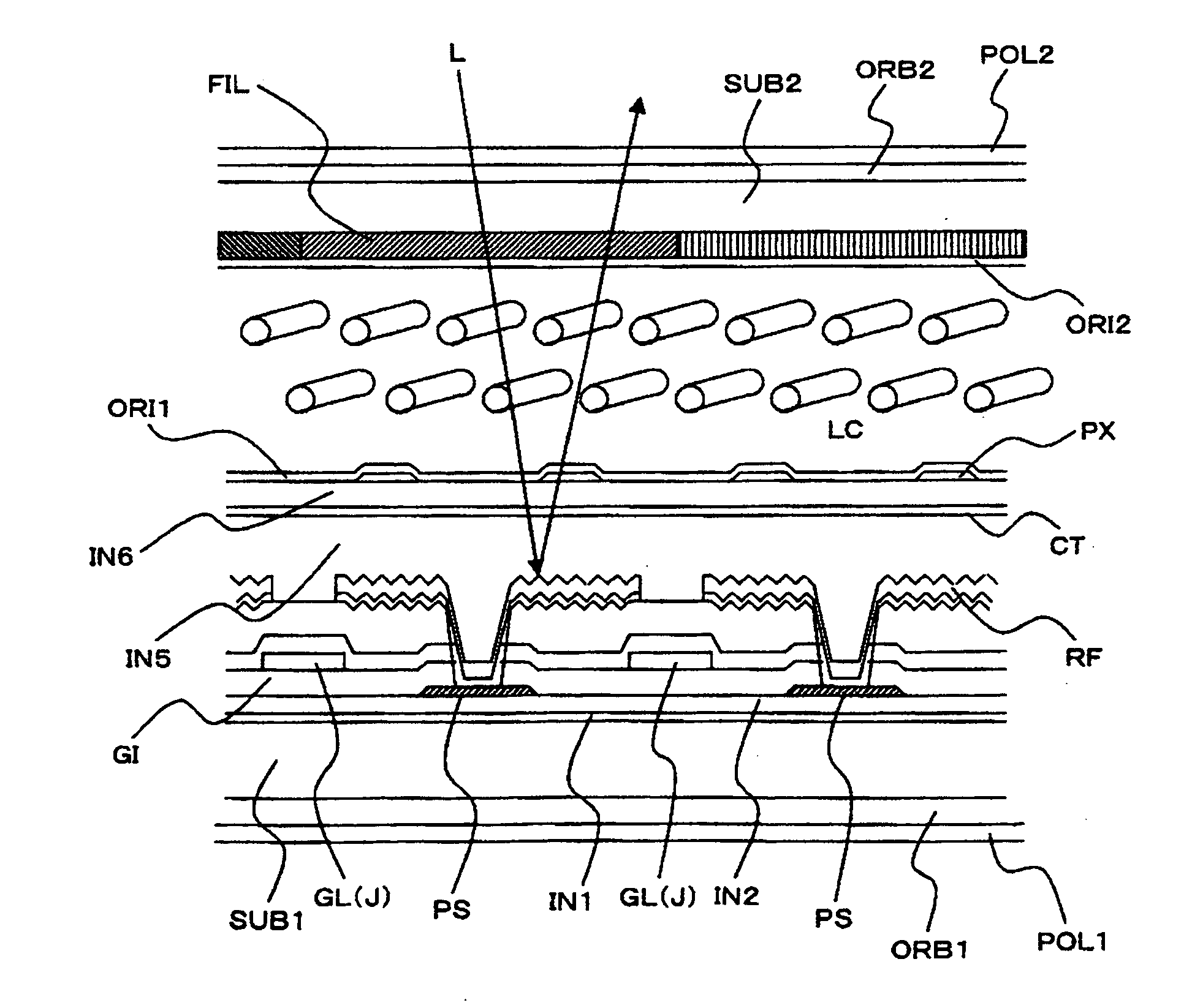
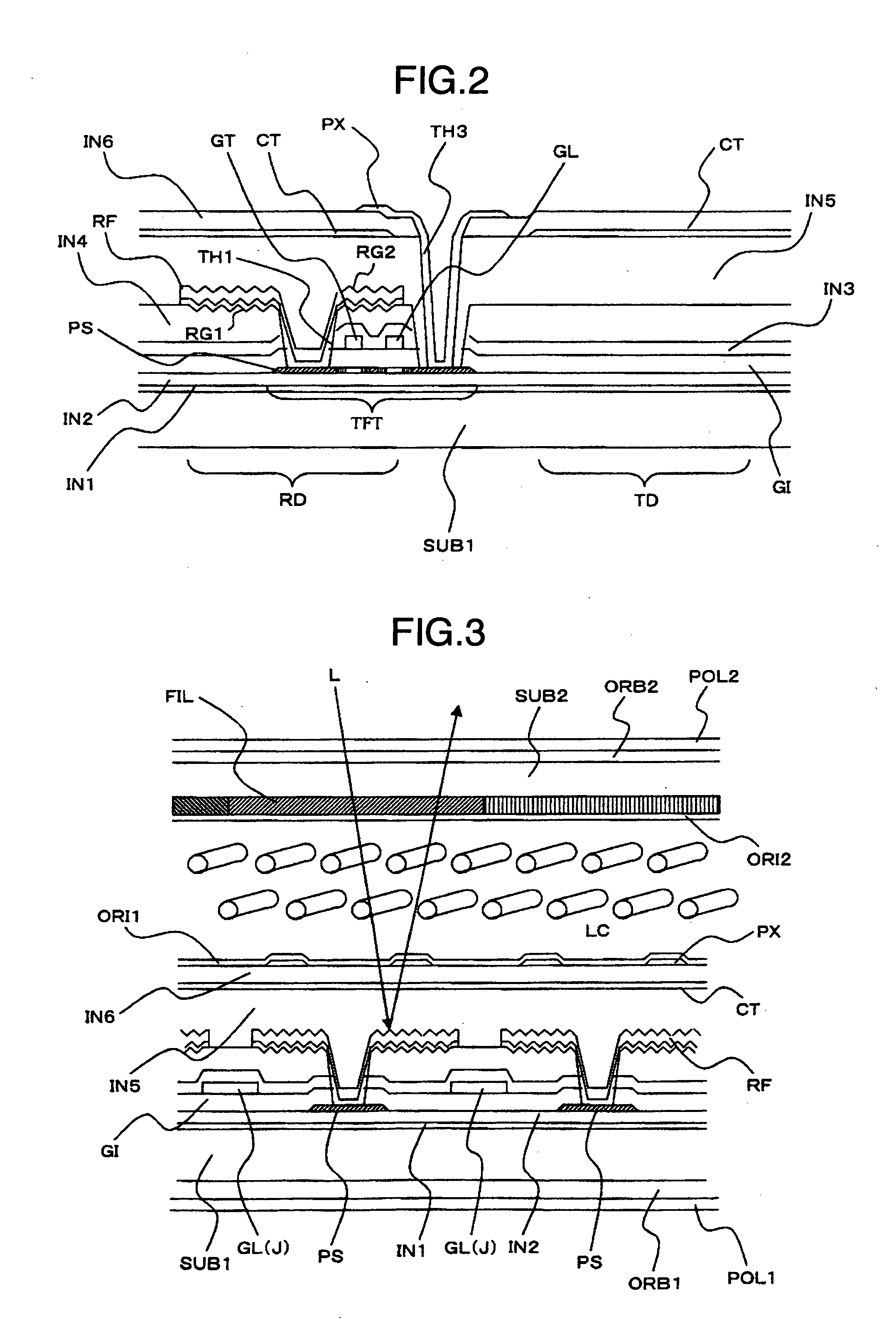
[0052]Referring first to FIG. 9, there is illustrated an equivalent circuit diagram showing a liquid crystal display apparatus according to embodiment 1 of this invention. The liquid crystal display apparatus in the present embodiment is of a so-called in plane switching type having substrates arranged to oppose to each other through a layer of liquid crystals and one of these substrates SUB1 is provided, in its pixel area close to or nearby the liquid crystal layer, with a pixel electrode and a counter electrode.

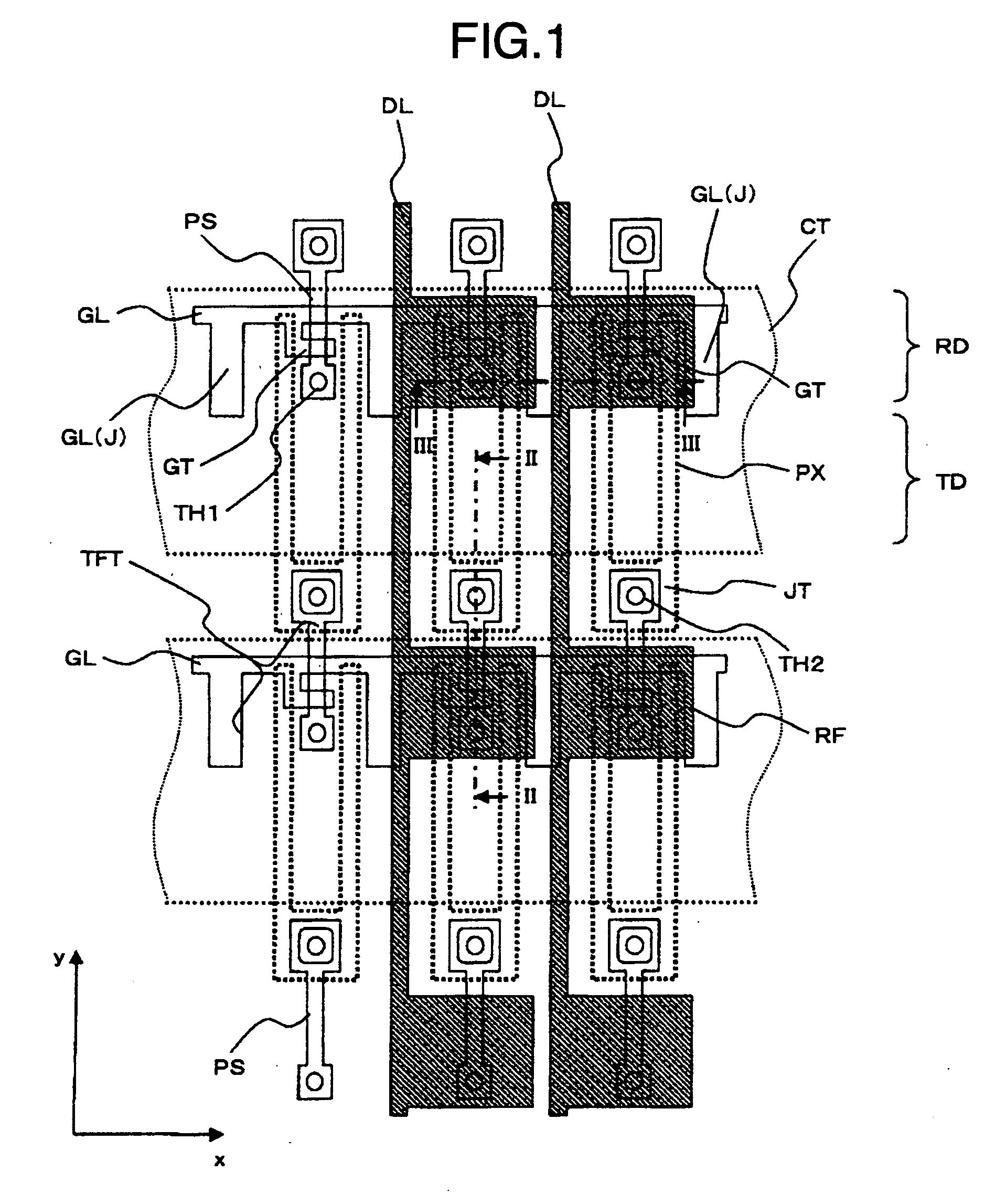
[0053]In FIG. 9, the substrate SUB1 is made of, for example, glass and on its surface confronting the liquid crystal layer, gate bus lines GL laid to extend in x direction and juxtaposed in y direction and drain bus lines DL extending in y direction and juxtaposed in x direction are formed.

[0054]A rectangular area surrounded by the gate bus lines GL and drain bus lines DL is an area in which a pixel PIX is formed. Then, individual pixels PIX thus formed ...

embodiment 2

(Equivalent Circuit)

[0122]Referring to FIG. 17, there is illustrated an equivalent circuit diagram showing a liquid crystal display apparatus according to embodiment 2 of the present invention. The FIG. 17 diagram corresponds to FIG. 9. The liquid crystal display apparatus as shown in FIG. 17 is constructed in a so-called longitudinal electric field type.

[0123]Firstly, this construction differs from the FIG. 9 construction in that the counter electrode CT is not formed on the side of substrate SUB1. This is because a counter electrode is formed on one surface, close to a layer of liquid crystals LC, of a substrate SUB2 which is arranged to oppose the substrate SUB1 via the liquid crystal layer.

[0124]Then, a storage line CPL is formed in association with individual pixels PIX and in each pixel, a holding capacitor C1 is formed between a pixel electrode PX and the storage line (capacitor electrode) CPL.

(Construction of Pixel)

[0125]Reference will now be made to FIG. 10 and FIGS. 11A to...


PUM

PropertyMeasurementUnit
light reflectionaaaaaaaaaa
transparentaaaaaaaaaa
light transmissionaaaaaaaaaa

Abstract

A liquid crystal display apparatus includes pixel electrodes each supplied with a video signal from a drain bus line through a thin-film transistor driven by a scanning signal from a gate bus line. The pixel includes at least a light reflection film within its area, the light reflection film is flush with the drain bus line, having its surface formed with concave and convex ruggedness segments, the pixel electrode is formed on the top of an insulator film formed to cover the light reflection film and having its surface flattened or leveled and an electrode overlapping the light reflection film and insulated from the pixel electrode is intervened in the insulator film.

Description

INCORPORATION BY REFERENCE[0001]The present application claims priority from Japanese application JP2007-163274 filed on Jun. 21, 2007, the content of which is hereby incorporated by reference into this application.BACKGROUND OF THE INVENTION[0002]The present invention relates to liquid crystal display apparatus and more particularly, to a so-called transreflective liquid crystal display apparatus having a light reflection domain in part of a pixel area.[0003]In the field of liquid crystal display apparatus, the transreflective liquid crystal display apparatus has been known as causing images to be recognized by using even a light source of external light such as for example the sun light.[0004]This type of liquid crystal display apparatus can be constructed by providing, for example, a light reflection domain having a light reflection film in addition to a light transmission domain for transmitting light from a backlight so that images may be recognized even when the backlight is t...

Claims


Application Information

Patent Timeline
Patent Type & Authority Applications(United States)
IPC IPC(8): G02F1/1335
CPCG02F1/133555G02F1/134363G02F1/136286G02F2001/133357G02F1/133357
Inventor SATO, TAKESHI
Owner PANASONIC LIQUID CRYSTAL DISPLAY CO LTD
Why Eureka
Try Eureka