

Very small spot-size light beam forming apparatus
- Summary
- Abstract
- Description
- Claims
- Application Information
AI Technical Summary
Benefits of technology
Problems solved by technology
Method used
Image

Examples
first embodiment
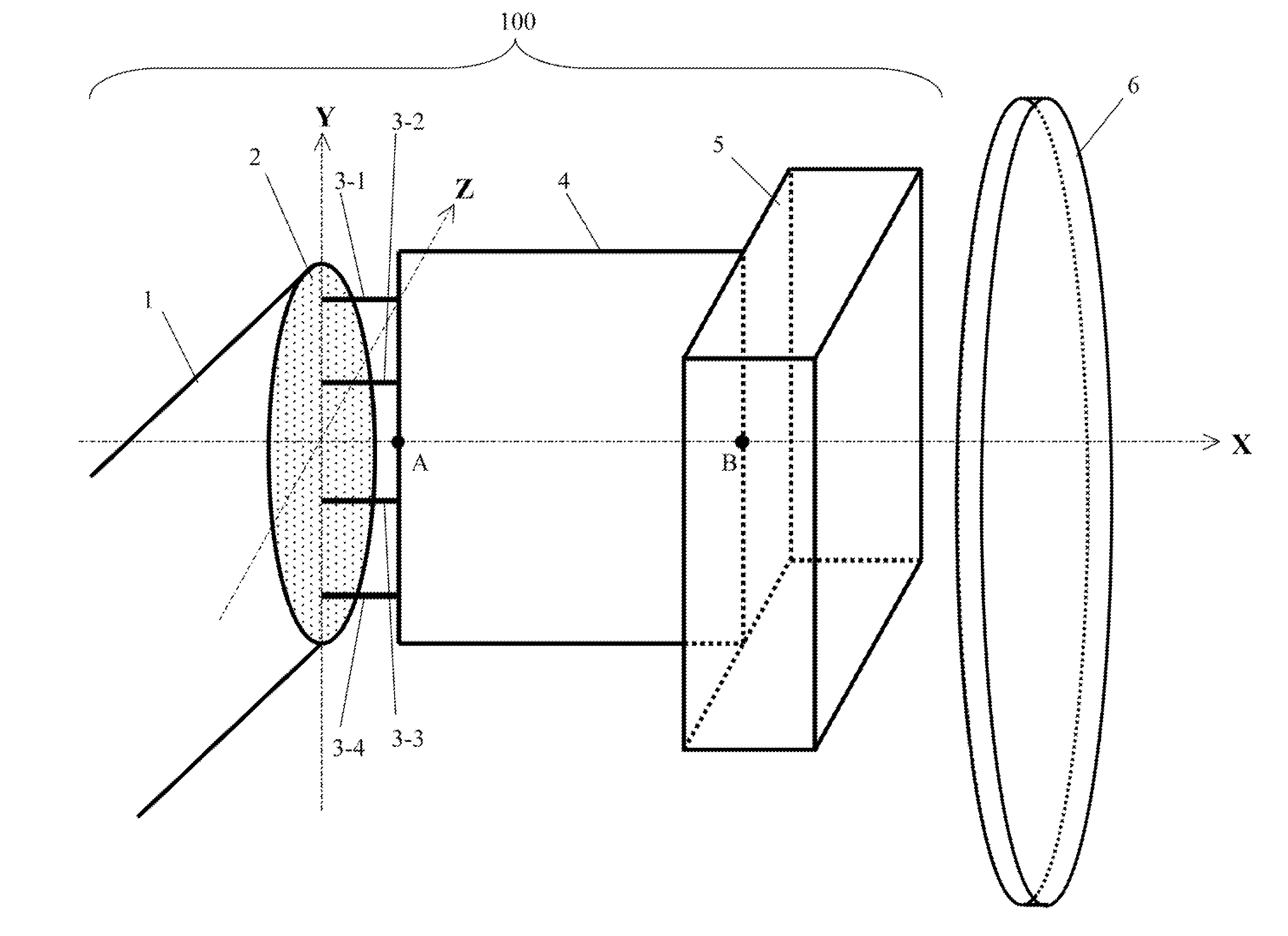
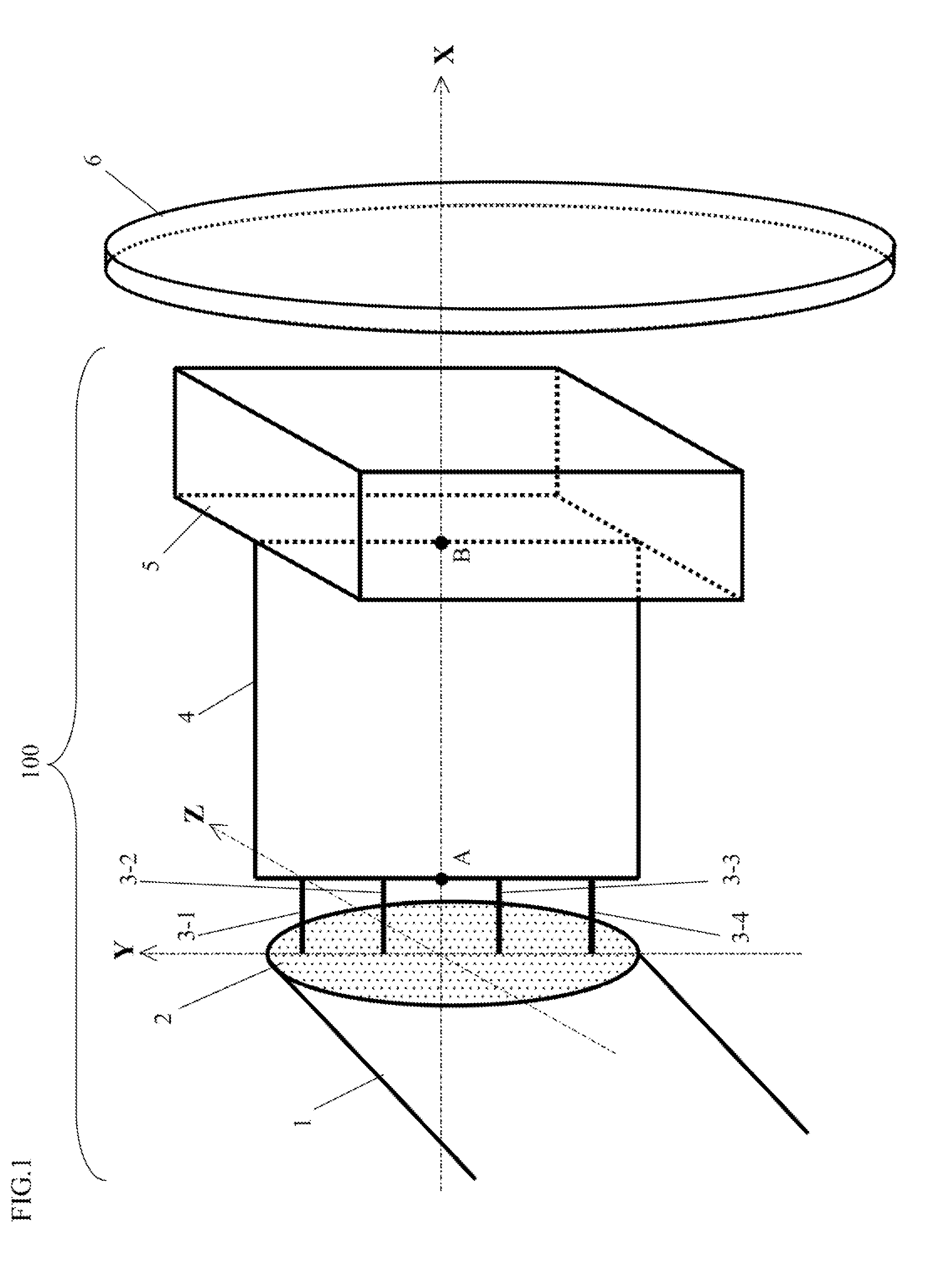
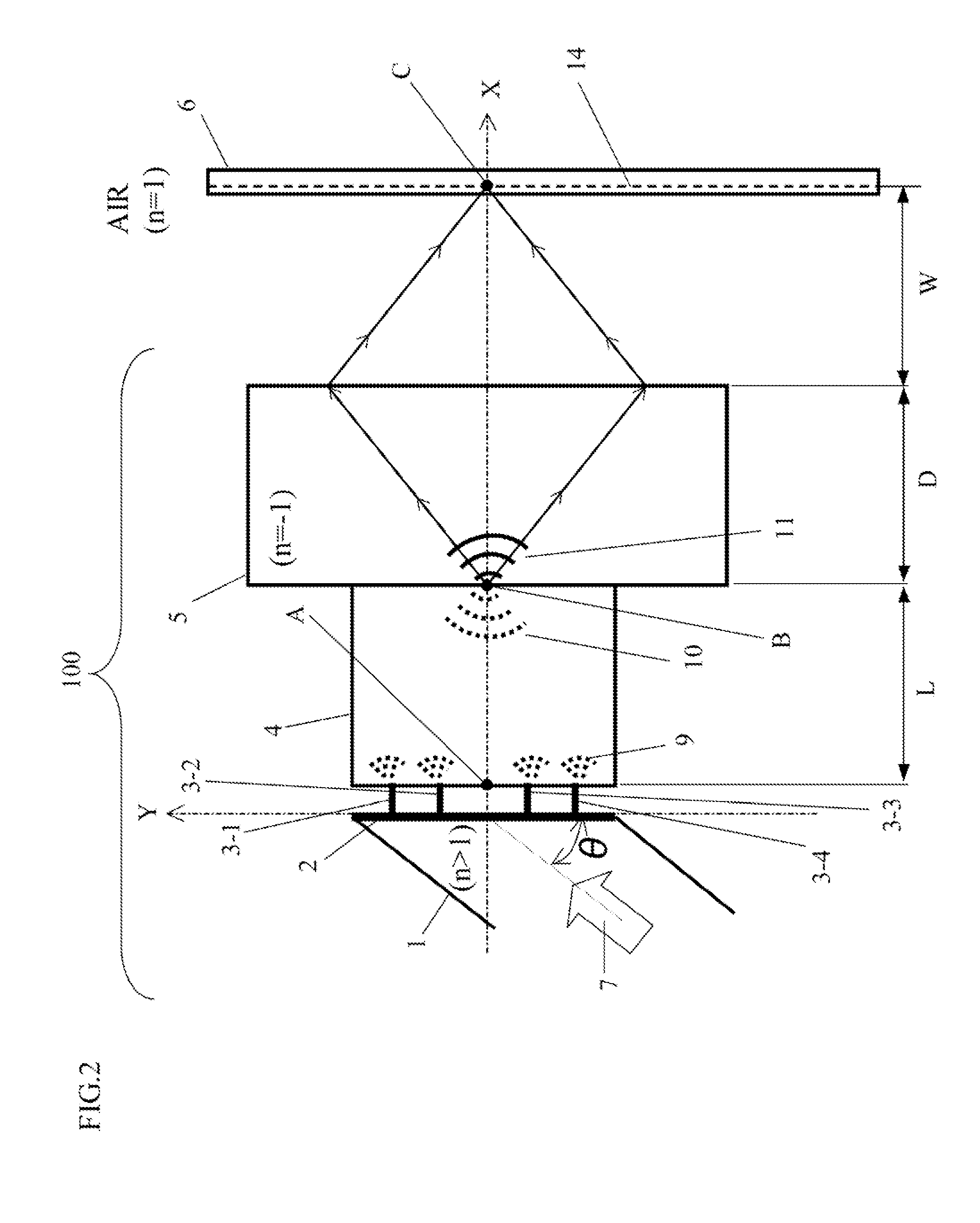
[0029]FIG. 1 is a perspective view illustrating an exemplary configuration of a very small spot-size light beam forming apparatus 100 according to a first embodiment of the present invention. FIG. 2 is an elevation view of the very small spot-size light beam forming apparatus 100 as viewed in the Z-direction shown in FIG. 1. Hereinafter, the first embodiment will be described with reference to FIGS. 1 and 2.
[0030]The very small spot-size light beam forming apparatus 100 comprises: an optical transmission path 1; a metal film 2; metal nano projections 3-1, 3-2, 3-3, and 3-4; a coupling unit 4; and a negative-refractive-index lens 5. The optical information storage disk 6 is not a component of the very small spot-size light beam forming apparatus 100. The optical transmission path 1 is an optical waveguide typified by an optical fiber. The metal film 2 is a film-shaped metal. The metal nano projections 3-1, 3-2, 3-3, and 3-4 are each a projection-shaped metal, and are each connected t...
second embodiment
[0037]FIG. 3 is a perspective view illustrating an exemplary configuration of a very small spot-size light beam forming apparatus 200 according to a second embodiment of the present invention. The very small spot-size light beam forming apparatus 200 is different from the very small spot-size light beam forming apparatus 100 (as shown in FIG. 1) of the first embodiment in that in the very small spot-size light beam forming apparatus 200 a coupling unit 25 is used instead of the coupling unit 4 of the first embodiment, and metal nano projections 3-5, 3-6, 3-7, and 3-8 are added. The optical information storage disk 6 is not a component of the very small spot-size light beam forming apparatus 200. Further, for the very small spot-size light beam forming apparatus 200, the same components as those of the very small spot-size light beam forming apparatus 100 are denoted by the same corresponding reference numerals, and the description thereof is not repeated.
[0038]As shown in FIG. 3, th...
third embodiment
[0045]FIG. 4 is a diagram illustrating a very small spot-size light beam forming apparatus 300 according to a third embodiment of the present invention. As shown in FIG. 4, the very small spot-size light beam forming apparatus 300 comprises an optical transmission path 52, three metal films 55, and three negative-refractive-index lenses 56. The optical information storage disk 6 is not a component of the very small spot-size light beam forming apparatus 300. The optical transmission path 52 is an optical waveguide typified by an optical fiber. The metal films 55 are each a film-shaped metal, and each has an opening 54 having the opening diameter smaller than a wavelength of an inputted light 51 propagating through the optical transmission path 52. The negative-refractive-index lenses 56 are each a lens (refer to Documents 4 and 5) having a negative refractive index, and are each a plane lens having two surfaces parallel with each other.
[0046]The optical transmission path 52 is conne...
PUM
 Abstract
Description
Claims
Application Information