X-ray radiation diaphragm and control method therefor, and ct device embodying same

Active Publication Date: 2008-12-25
SIEMENS HEATHCARE GMBH
View PDF9 Cites 26 Cited by
  • Summary
  • Abstract
  • Description
  • Claims
  • Application Information

AI Technical Summary

Benefits of technology

[0011]An object of the present invention is to provide a device and a method that enable the

Problems solved by technology

In comparison to the first cited method, the electromechanical effort is very slight.
T

Method used


Image

  • X-ray radiation diaphragm and control method therefor, and ct device embodying same
  • X-ray radiation diaphragm and control method therefor, and ct device embodying same
  • X-ray radiation diaphragm and control method therefor, and ct device embodying same

Examples


Embodiment Construction

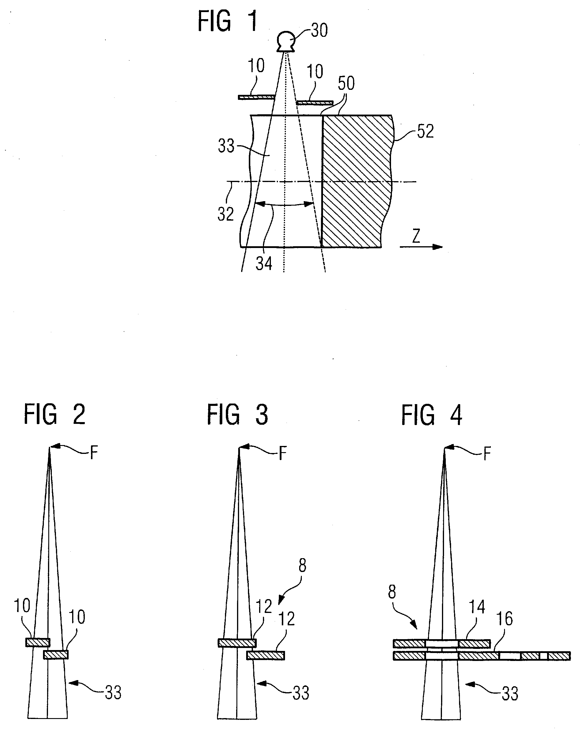
[0031]One possible design of a device with dynamic collimation according to the invention is illustrated using FIGS. 3 and 4.

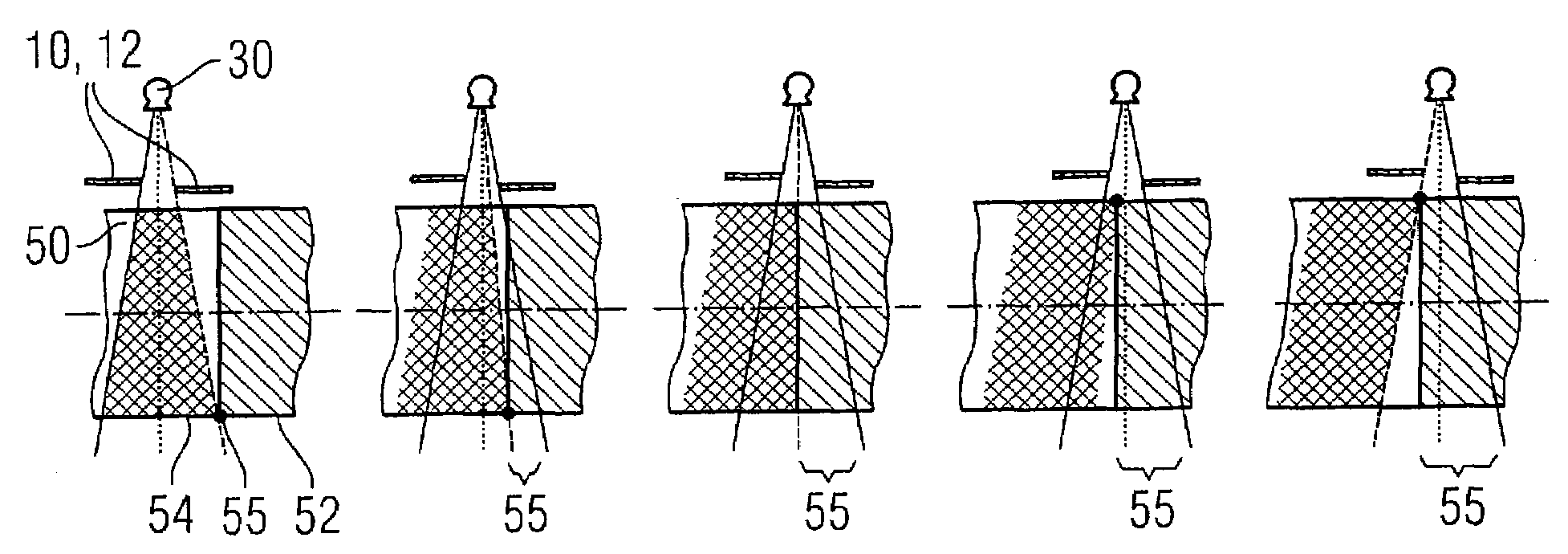
[0032]FIG. 1 illustrates the general known prior art. The fan beam 33 is generated by means of the x-ray tube 30. Additional scattered radiation arises in the apparatus. The beam 33 is limited in the x-direction (and therefore in the scan direction) by means of the diaphragm jaws 10 of the collimator, whereby the fan angle 34 is generated. The examination subject or the patient 50 is located in the rotation axis (z-direction) of a computed tomography apparatus 32. Furthermore, a reconstruction region 52 is shown in order to make the comprehension of FIG. 5 through 7 easier. This is the region of the patient that is examined from which data are acquired and evaluated.

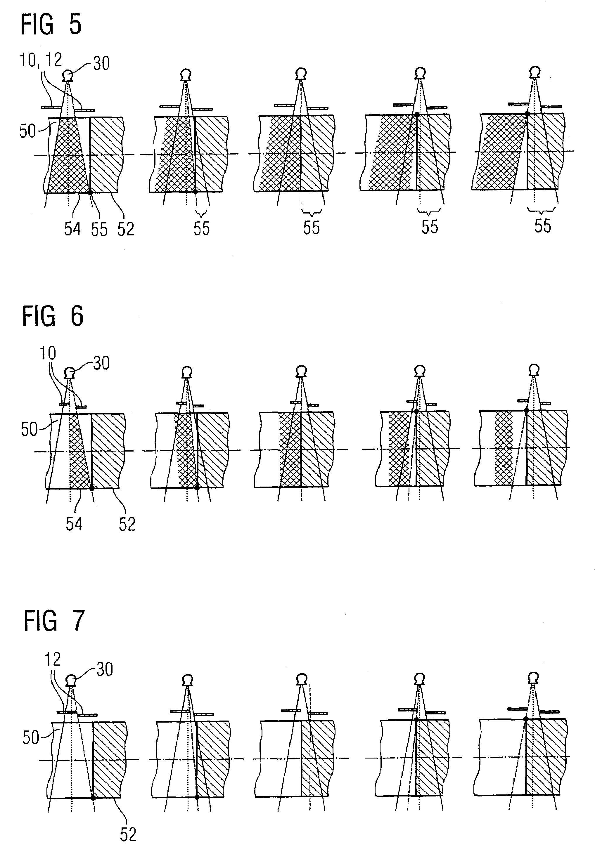
[0033]FIG. 5 (prior art) shows which regions of the examination subject or of the patient 50 are exposed to the radiation given static collimation according to the variants described above (see FIG...


PUM


Abstract

A collimator device has at least one masking device that is adjustable between two end positions for collimation of a beam fan in an x-ray CT device, wherein the x-ray fan is schematically not masked in a first end position. The x-ray beam is more than half-masked in a second end position of the masking device. In a method for operation of such a collimator device as well as an x-ray CT device for examination of a subject having an x-ray source, a collimator device, and a control device for regulation of the aperture width of the masking device, an x-ray detector is arranged opposite the x-ray source and the collimator device and that detects the x-rays modified due to the intervening examination subject; and an image construction device reconstructs an image of the examination subject therefrom.

Description

BACKGROUND OF THE INVENTION[0001]1. Field of the Invention[0002]The present invention concerns a radiator diaphragm, i.e., a device for collimation of x-rays of the type having at least one masking element that is adjustable between two end positions. Furthermore, the invention concerns a method to control this radiator diaphragm or collimator device and an x-ray CT device embodying such a radiator diaphragm or collimator device according to the invention.[0003]2. Description of the Prior Art[0004]Collimation is the procedure for directing light beams or x-rays to propagate in a parallel manner. A lens that directs the light of a punctiform (in terms of its focal point) light source parallel to the optical axis of the lens is used for collimation of light rays. This parallel beam can be used as a replacement for a light source at infinite distance. Diaphragm devices (known as radiator diaphragms) are typically used for collimation or of x-rays in CT apparatuses (computed tomography ...

Claims


Application Information

Patent Timeline
IPC IPC(8): G21K1/04
CPCA61B6/06G21K1/04A61B6/027
Inventor KUEHN, ULRICHWOLF, HEIKO
Owner SIEMENS HEATHCARE GMBH
Why Eureka
Try Eureka