Image capturing apparatus and control method therefor

a technology of image capture and control method, which is applied in the direction of camera focusing arrangement, printers, instruments, etc., can solve the problems of inconvenient high-speed focus adjustment operation, bulky devices, and high cost, and achieve the effect of improving the detection capability of focus detection portion and performing more accurate focus detection

Active Publication Date: 2008-12-25
CANON KK
View PDF8 Cites 85 Cited by
  • Summary
  • Abstract
  • Description
  • Claims
  • Application Information

AI Technical Summary

Benefits of technology

[0013]The present invention has been made to overcome the conventional drawbacks, and has as its object to improve the detection capability of a focus detection portion and perform more accurate focus detection.

Problems solved by technology

However, the contrast detection method, also called a hill-climbing detection method, is not suitable for a high-speed focus adjustment operation because the evaluation value is obtained while slightly moving the photographing optical system, and the photographing optical system needs to be moved until it is revealed that the evaluation value was maximum.
This structure makes the device bulky and expensive.
However, according to any of these references, luminance corresponding to each focus detection portion is too low to reliably detect the luminance distribution of an object.
It is, therefore, difficult to perform accurate focus detection.

Method used


Image

  • Image capturing apparatus and control method therefor
  • Image capturing apparatus and control method therefor
  • Image capturing apparatus and control method therefor

Examples


first embodiment

[0048]FIGS. 1 to 20 are views for explaining an image capturing apparatus and control method therefor according to the embodiment of the present invention. The operation of the embodiment will be described with reference to these drawings.

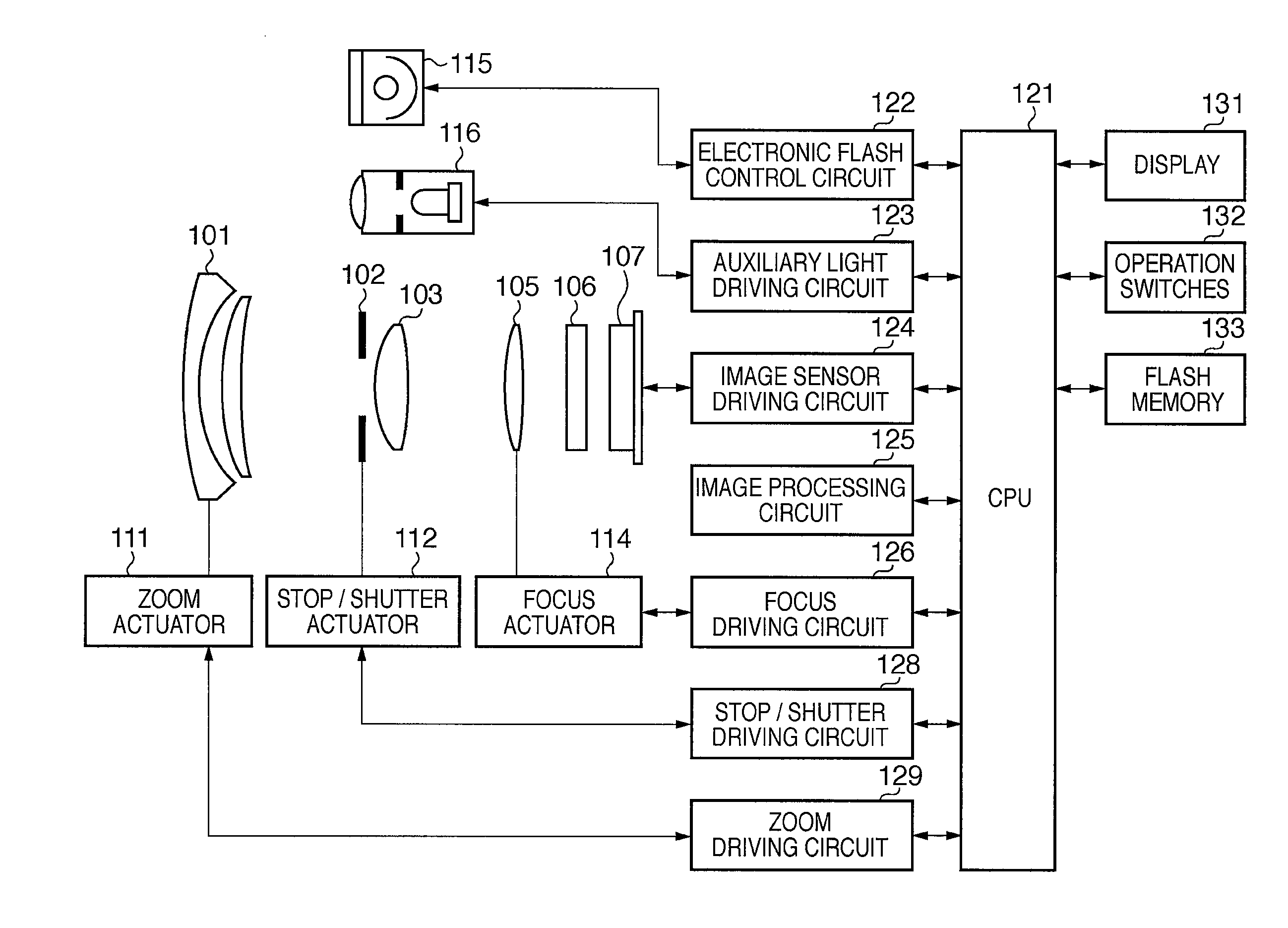
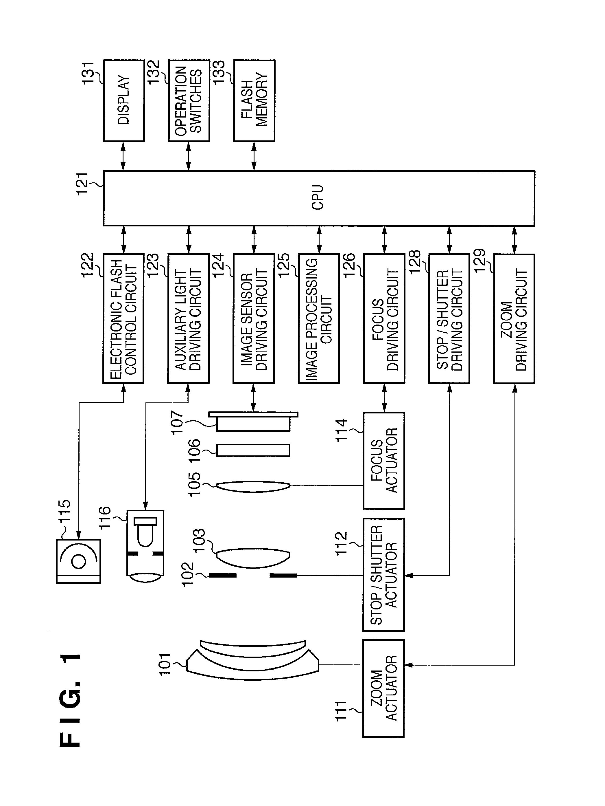
[0049]FIG. 1 is a view of the configuration of the image capturing apparatus according to the preferred embodiment of the present invention. FIG. 1 shows an electronic camera configured by integrating a camera body having an image sensor with a photographing optical system. In FIG. 1, a first lens group 101 is arranged on the first stage of the photographing optical system (image forming optical system), and is held reciprocally along the optical axis. A stop / shutter 102 adjusts the aperture diameter to adjust the light quantity in shooting. The stop / shutter 102 also functions as a shutter for adjusting the exposure time when shooting a still image. The stop / shutter 102 and a second lens group 103 reciprocate together along the optical axis to achi...

second embodiment

[0123]In the first embodiment, paired lateral defocus detection pixels or paired longitudinal defocus detection pixels are assigned to the positions of R and B pixels diagonally adjacent to each other. In the second embodiment, focus detection pixels are assigned to the positions of pixels of a single color, i.e., only R or B pixels. The arrangement of the second embodiment will be explained with reference to FIGS. 21 to 25B.

[0124]FIG. 21 is a view showing a focus detection pixel array according to the second embodiment, and corresponds to FIG. 9 in the first embodiment. In the first embodiment shown in FIG. 9, the focus detection pixels SHA, SHB, SVC and SVD are assigned to the positions of R and B pixels diagonally adjacent to each other among image sensing pixels having the Bayer array. In the second embodiment shown in FIG. 21, focus detection pixels are assigned to only B pixels in the Bayer array. More specifically, in each of the top left block BLKh(1,1) and lower right block...

third embodiment

[0138]In the first and second embodiments, two focus detection pixels are paired, one pixel receives a beam having passed through one pupil in the pupil area divided into two, and the other pixel receives a beam having passed through the other pupil. In contrast, the third embodiment will describe an image sensor in which a beam having passed through the pupil area divided into two is received by one pixel to output the signal.

[0139]The third embodiment will be described with reference to FIGS. 26 and 27.

[0140]FIG. 26 is a view showing a focus detection pixel array according to the third embodiment, and corresponds to FIG. 9 in the first embodiment. In the first embodiment shown in FIG. 9, the focus detection pixels SHA, SHB, SVC and SVD are assigned to the positions of R and B pixels diagonally adjacent to each other among image sensing pixels having the Bayer array. In the third embodiment shown in FIG. 26, a focus detection pixel is assigned to only one R pixel in each block of 1...


PUM


Abstract

An image capturing apparatus includes an image sensor, composition unit, coupling unit, and arithmetic unit. The image sensor has a plurality of pupil-divided focus detection portions each formed from a first focus detection pixel and second focus detection pixel. The composition unit composites signals output from the first focus detection pixels to obtain a first composite signal, and composites signals output from the second focus detection pixels to obtain a second composite signal in each of sections assigned to the image sensor to include a plurality of focus detection portions. The coupling unit couples first composite signals to obtain a first coupled signal, and couples second composite signals to obtain a second coupled signal in the plurality of sections. The arithmetic unit calculates the defocus amount of an image forming optical system on the basis of the first and second coupled signals.

Description

BACKGROUND OF THE INVENTION[0001]1. Field of the Invention[0002]The present invention relates to an image capturing apparatus using an image sensor capable of capturing at least either a still image or moving image by two-dimensionally arrayed photoelectric conversion elements, and a control method therefor.[0003]2. Description of the Related Art[0004]A contrast detection method (called a blur detection method) and a phase-difference detection method (called a defocus detection method) have been proposed as general methods using a beam having passed through a photographing optical system in automatic focus detection / adjustment of an image capturing apparatus.[0005]The contrast detection method is often used in a video movie camera (camcorder) for recording a moving image, and an electronic still camera. The image sensor is used as a focus detection sensor. This method pays attention to the output signal of the image sensor, especially information (contrast information) of a high-fre...

Claims


Application Information

Patent Timeline
Patent Type & Authority Applications(United States)
IPC IPC(8): G03B13/36H04N5/228
CPCG02B7/08G02B7/285G03B13/36H04N5/23212H04N5/23216H04N5/23219H04N5/37452H04N23/672H04N23/62H04N23/611H04N25/771H04N25/134
Inventor ONUKI, ICHIRO
Owner CANON KK
Why Eureka
Try Eureka