

Method and Apparatus For Limiting Peer-to-Peer Communication Interference
a peer-to-peer communication and interference technology, applied in the field of mobile terminals, can solve the problems of network operators being expected to require control of radio resources and interference in the network, and the solution of peer-to-peer communication does not account for this need, so as to achieve the effect of increasing the power level
- Summary
- Abstract
- Description
- Claims
- Application Information
AI Technical Summary
Benefits of technology
Problems solved by technology
Method used
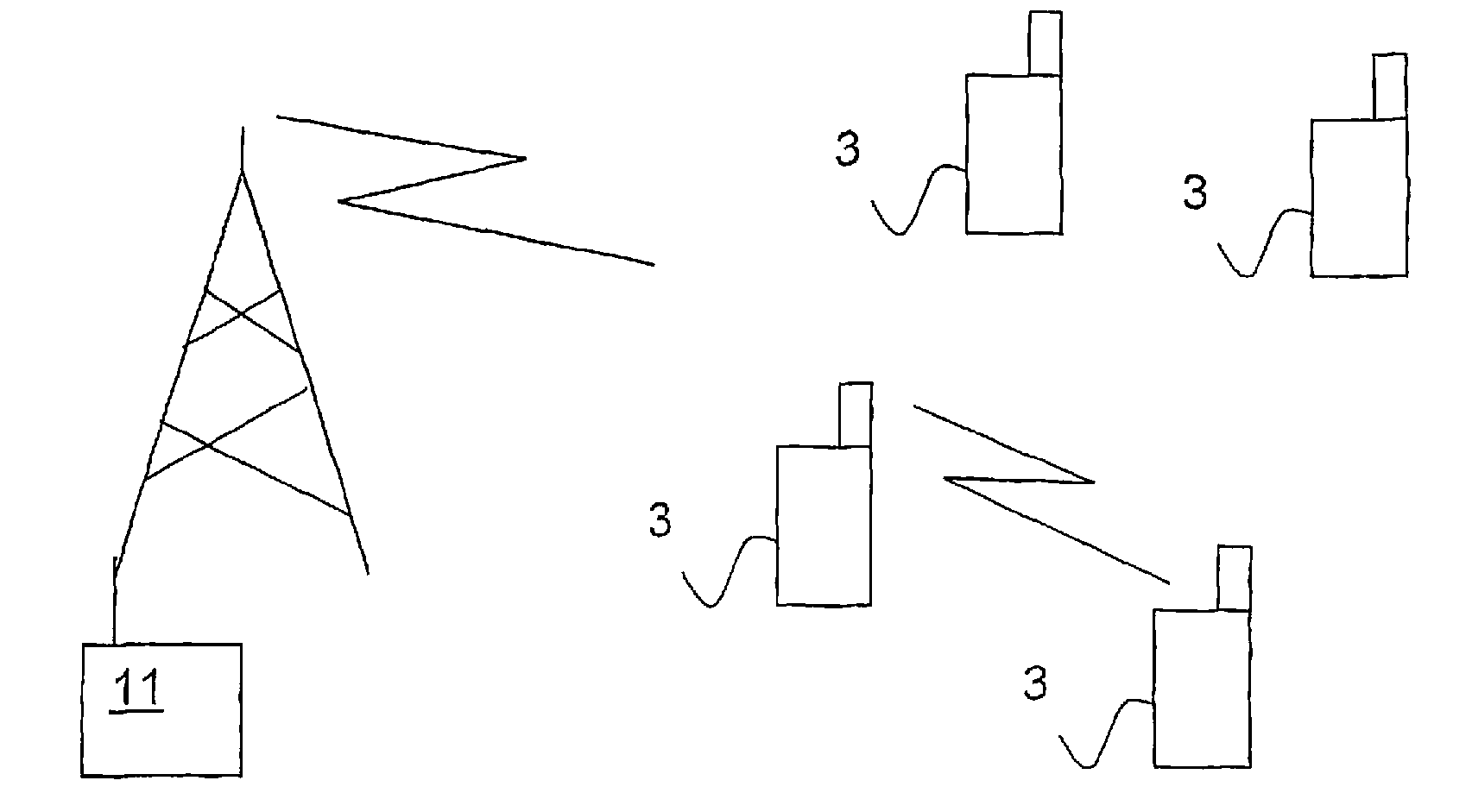
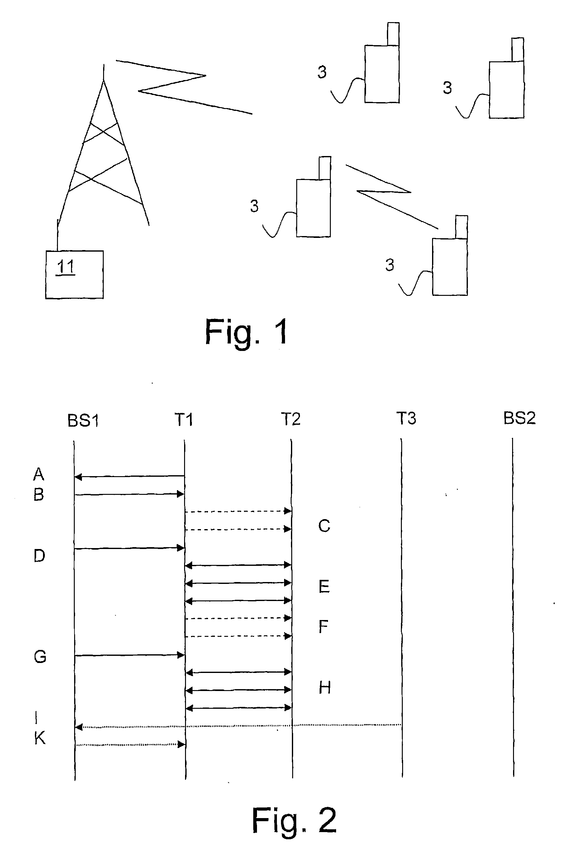
Image

Examples
first embodiment
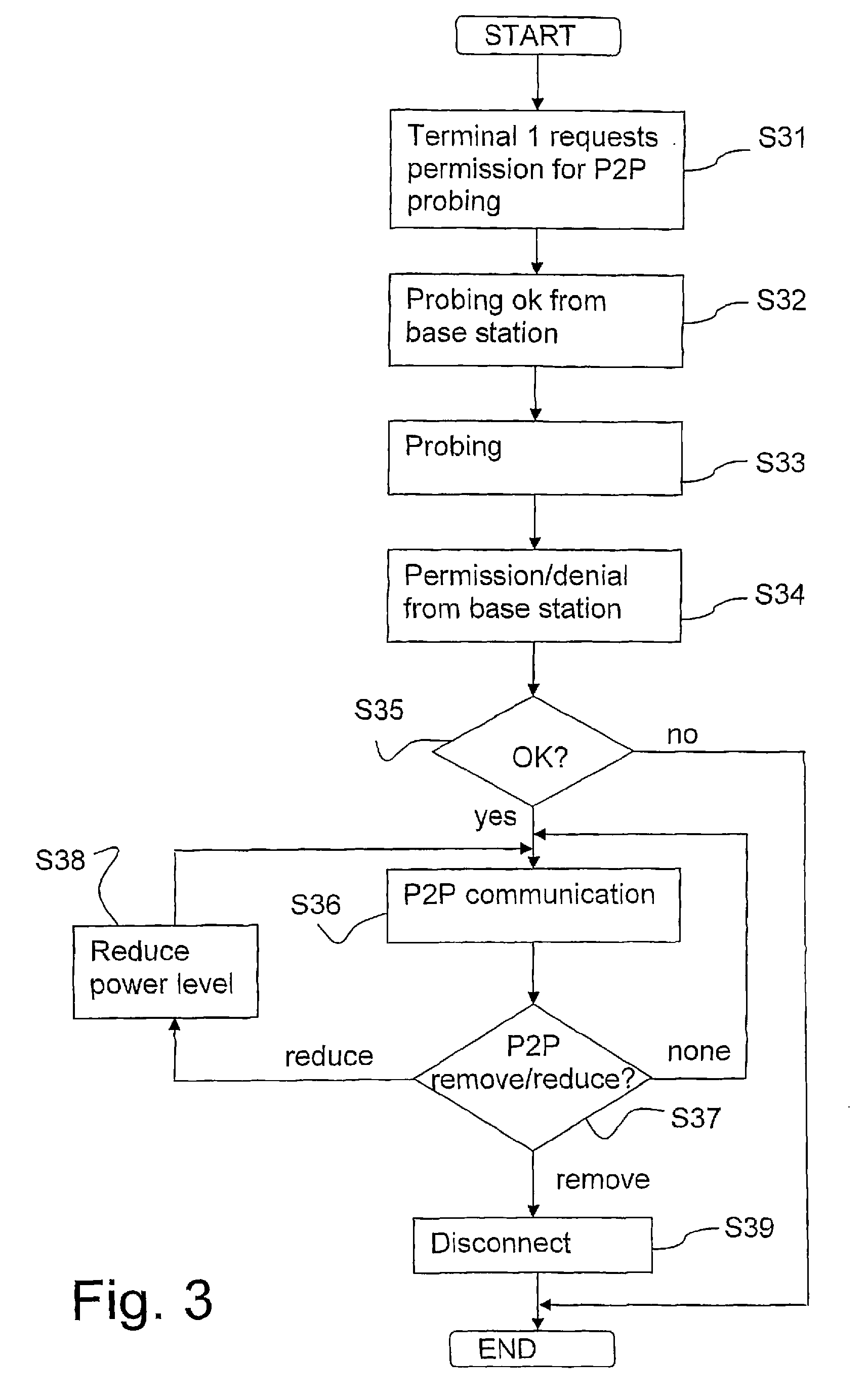
[0066]FIG. 3 is a flow chart of the invention as seen by the mobile terminal.
[0067]In step S31 the first, or master, terminal requests permission to start probing for peer-to-peer communication with another terminal.
[0068]In step S32 the first terminal receives a “probing ok” signal from the base station.
[0069]In step S33 the first and second terminals perform probing.
[0070]In step S34 a permission signal or a denial signal is received from the base station in both the first and the second terminal, or just in the first terminal.
[0071]In step S35 the signal received from the base station is evaluated. If yes go to step S36; if no, end of procedure.
[0072]In step S36 peer-to-peer communication is performed between the first and the second terminal.
[0073]In step S37 the terminal checks if a remove signal or a reduce signal has been received from the base station. If a remove signal has been received, go to step 39; if a reduce signal has been received, go to step 38; if no signal has b...
second embodiment
[0080]FIG. 4 is a flow chart of the invention as experienced by the terminal.
[0081]In step S41 the first, or master, terminal requests permission to start probing for peer-to-peer communication with another terminal.
[0082]In step S42 the first terminal receives a “probing ok” signal from the base station.
[0083]In step S43 the first and second terminal perform probing.
[0084]In step S44 a permission signal or a denial signal is received from the base station in both the first and the second terminal, or just in the first terminal.
[0085]In step S45 the signal received from the base station is evaluated. If yes go to step S46; if no, end of procedure.
[0086]In step S46 peer-to-peer communication is performed between the first and the second terminal.
[0087]In step S47 the terminal checks if an ok signal has been received from the base station. If an ok signal has been received, return to step S46; if no ok signal has been received, go to step S48.
[0088]In step 48 the peer-to-peer communic...
PUM
 Abstract
Description
Claims
Application Information