Catheter Steering Device

a technology of catheter and steering device, which is applied in the direction of catheters, external electrodes, sensors, etc., can solve the problems of complex design and difficult manufacturing, and achieve the effect of facilitating steering and shape forming

Inactive Publication Date: 2008-12-25
CATHRX LTD
View PDF10 Cites 41 Cited by
  • Summary
  • Abstract
  • Description
  • Claims
  • Application Information

AI Technical Summary

Benefits of technology

[0019]According to a second aspect of the invention, there is provided a catheter steering and shape forming device which comprises an elongate element having a proximal end and a distal end and defining a longitudinal axis with material...

Problems solved by technology

This is a complex design w...

Method used


Image

  • Catheter Steering Device
  • Catheter Steering Device
  • Catheter Steering Device

Examples


Embodiment Construction

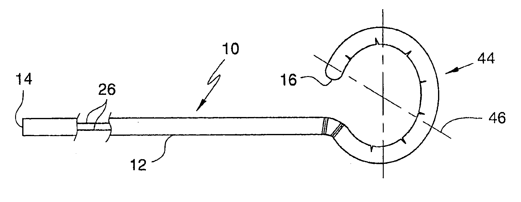
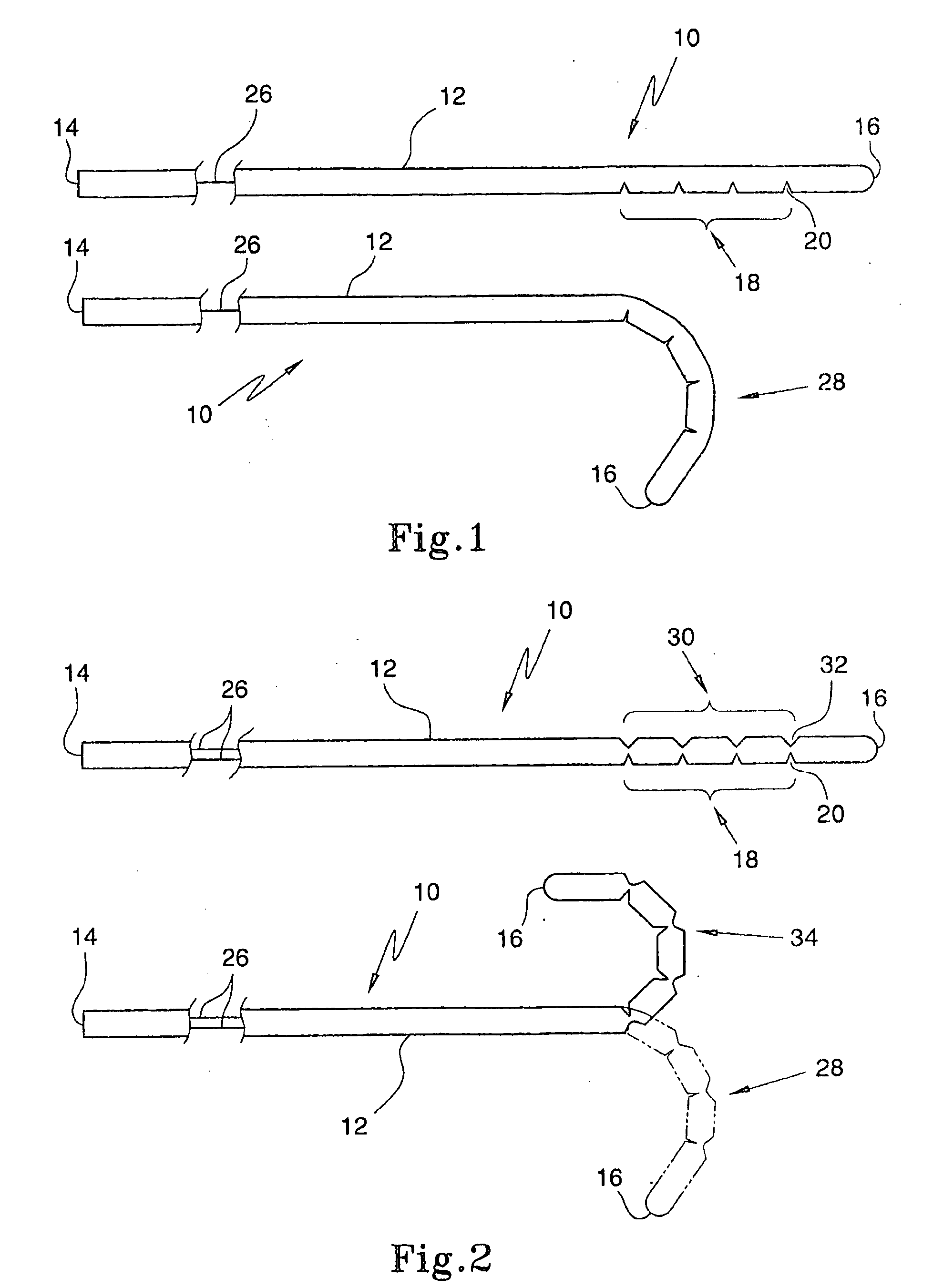
[0032]In FIG. 1 of the drawings, reference numeral 10 generally designates an exemplary embodiment of a catheter steering and shape forming device. For the sake of brevity, the catheter steering and shape forming device will be referred to below as the “steering device” or simply as the “device”. The steering device 10 comprise an elongate element 12 having a proximal end 14 and a distal end 16 and defining a longitudinal axis.

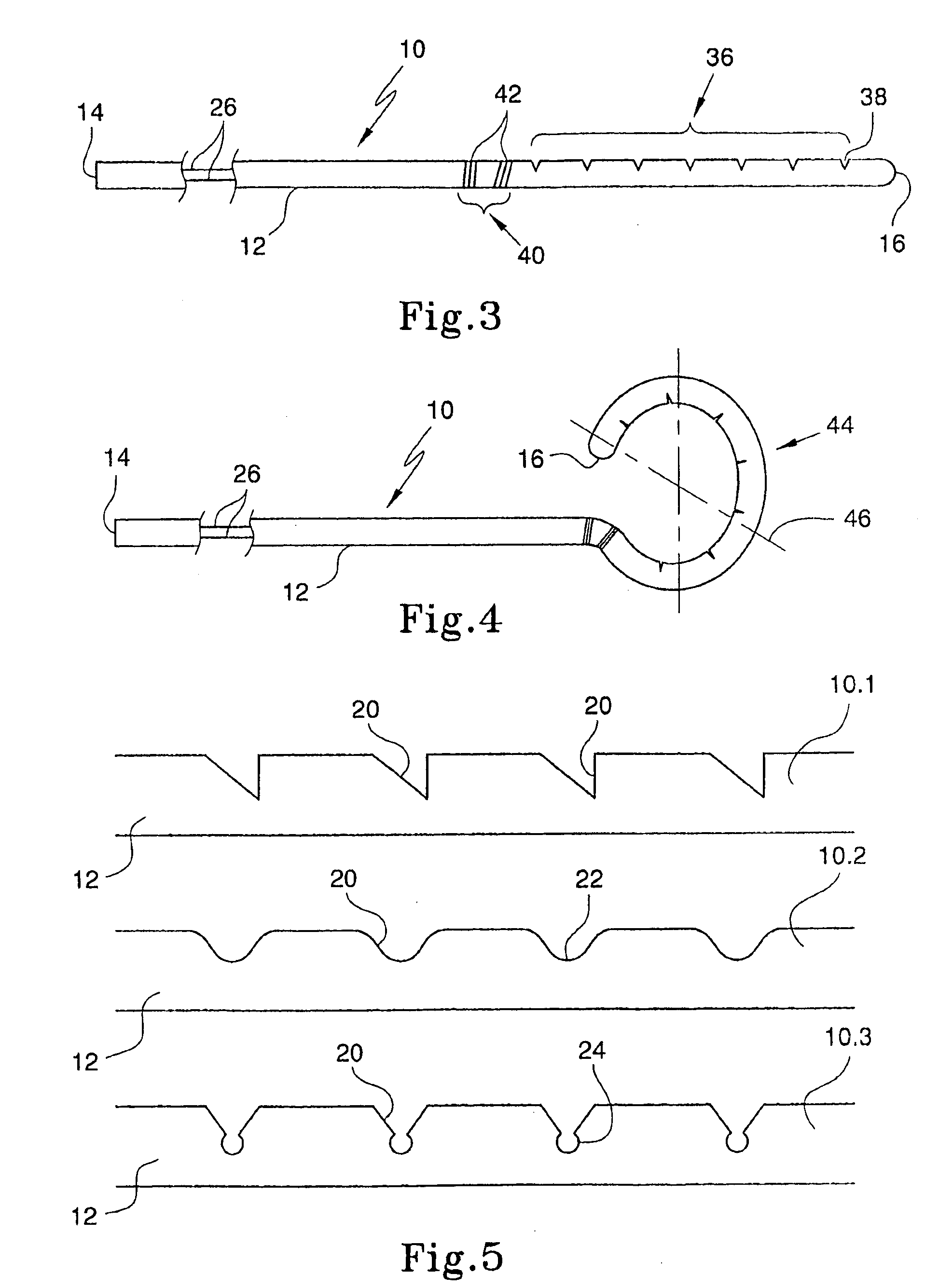
[0033]A bending facilitating arrangement, formed by the removal of material in ,n interrupted manner in a longitudinal direction, to form of a group 18 of notches 20 is arranged proximate the distal end 16 of the elongate element 12. Each notch 20 extends transversely to the longitudinal axis of the elongate element 12 and has non-parallel sides. In particular, each notch 20 is substantially V-shaped when viewed from an end of the notch 20.

[0034]As shown in FIG. 5 of the drawings, the notches 20 could, firstly, be non-symmetrical about a median plane, as shown...


PUM


Abstract

A catheter steering and shape forming device (10) comprises an clongate element (12) having a proximal end (14) and a distal end (16) and defining a longitudinal axis. A plurality of longitudinally spaced, transversely extending notches (20) is formed in the clongate element (12, the notches (20) having non-parallel sides and the notches (20) being arranged in at least one group (18) proximate the distal end (16) of the clongate element (12).

Description

CROSS-REFERENCE TO RELATED APPLICATIONS[0001]The present application claims priority from U.S. Provisional Patent Application No. 60 / 558299 filed on 30 Mar. 2004, the contents of which are incorporated herein by reference.FIELD OF THE INVENTION[0002]This invention relates to steering and shape forming devices for medical equipment. More particularly, the invention relates to a catheter steering and shape forming device.BACKGROUND TO THE INVENTION[0003]Electrophysiology catheters are medical devices used for measuring electrical signals within the heart in the diagnosis of arrhythmias. Certain types of these catheters may also be used for treating arrhythmias through ablative techniques.[0004]Generally, to access the region of the heart to be treated, the catheter is inserted through the femoral vein of the patient. The tip of the catheter therefore needs to be steered through the vascular system of the patient to the desired location. Similarly, the tip needs to be steered through t...

Claims


Application Information

Patent Timeline
IPC IPC(8): A61M25/01A61B1/00A61B5/042A61M25/00A61N1/05A61N1/18
CPCA61B5/042A61M25/0054A61M25/0138A61M25/0147A61M2025/0161A61M2025/0163A61N2001/0578A61B5/283
Inventor CHONG, EVAN K.
Owner CATHRX LTD
Why Eureka
Try Eureka