
Interconnect implementing internal controls

a technology of internal control and interconnection, applied in the direction of micro-instruction address formation, memory address/allocation/relocation, instruments, etc., can solve the problems of increasing traffic and routing congestion, increasing design and verification complexity, and software and system functional blocks

Active Publication Date: 2008-12-25
META PLATFORMS TECH LLC
View PDF50 Cites 70 Cited by
  • Summary
  • Abstract
  • Description
  • Claims
  • Application Information

AI Technical Summary

Benefits of technology

[0007]A method, apparatus, and system are described, which generally relate to an integrated circuit having an interconnect that implements internal controls. The interconnect may maintain transaction path order to support outstanding transactions to multiple targets while maintaining transaction ordering; maintain request path order; maintain response path order; interleave channels in an aggregate target with unconstrained burst sizes; have configurable parameters for channels in an aggregate target and mapping of address regions onto the one or more aggregate targets; chop individual transactions whose data address sequence within that transaction crosses an interleaved channel address boundary in an aggreg...

Problems solved by technology

This forced the software and system functional block to have to be aware of the organization and structure of the memory system when generating initiator requests.
In the traditional approach, the traffic may be split deeply in the memory subsystem in central routing units, which increases traffic and routing congestion, increases design and verification complexity, eliminates topology freedom, and increases latencies.
The created centralized point can act as a bandwidth choke point, a routing congestion point, and a cause of longer propagation path lengths that would lower achievable frequency and increase switching power consumption.

Method used


Image

  • Interconnect implementing internal controls
  • Interconnect implementing internal controls
  • Interconnect implementing internal controls

Examples


case 1

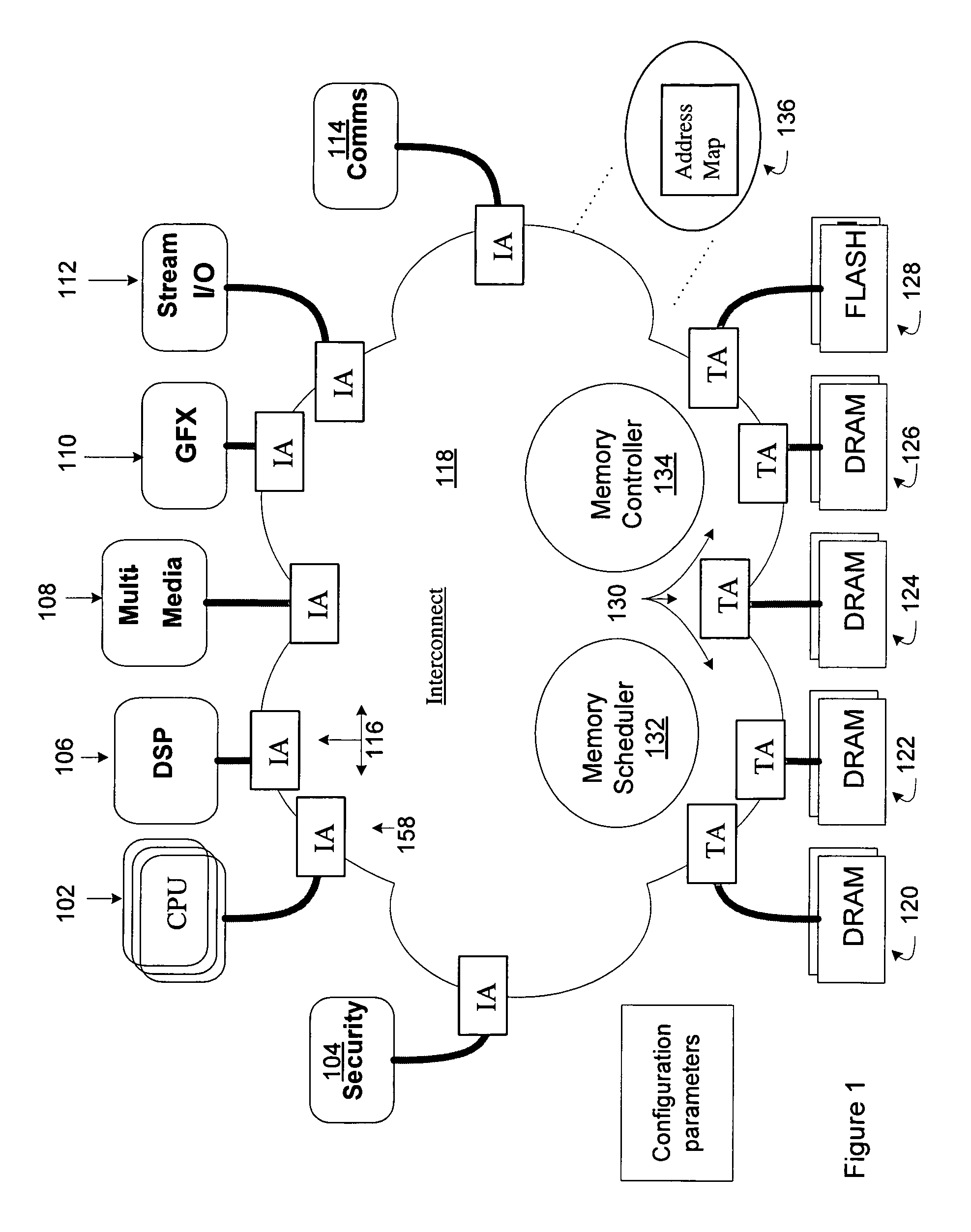
[0158] An outgoing branch carries target threads (i.e., the initiator threads to target threads mapping happens at this thread splitter module). In this case, each target thread needs its own turnaround queue. Whenever an m_ack_req signal is set to 1 on the dlout for the corresponding thread, the turnaround queue stores which (incoming) thread the acknowledge signal belongs to. When an s_ack_req_return signal is set high on the dlout, the turnaround queue is popped and routes the s_ack_req_return signal back to the correct ACU.

case 2

[0159] An outgoing branch carries initiator threads (i.e., no dynamic thread mapping) and the serialization thread merger unit is within the same cycle boundary. In this case, if the outgoing request has m_ack_req set (from the RS buffer, the signal won't be on the dlout) and the request is successfully sent, an s_ack_req_return is generated and sent to the corresponding ACU for that initiator thread. Thus, the serialization merger is within the same cycle boundary, so accept signal can be used as ack_return.

case 3

[0160] In this case the outgoing branch carries initiator threads and the serialization thread merger unit is in another cycle boundary. In other words, there is a PP between this RS branch and the serialization merger. In this case, the s_ack_req_return signal will be present for some or all of the initiator threads. If the signal is not present, there will not be an ACU for that thread. The s_ack_req_return[thread] signal bit needs to be sent directly to the ACU. Thus, the serialization merger is in another cycle boundary, so ack_return_ signals are present and can be used directly.

[0161]Some thread splitter threads may have m_ack_req signals on outgoing initiator threads without a corresponding ACU or a corresponding s_ack_req_return signal. In this case, the initiator thread is not doing channel splitting, but some downstream thread splitter unit is performing channel splitting.

[0162]If the RS din link has s_ack_req_return, then dlout link's s_ack_req_return value needs to be pa...


PUM


Abstract

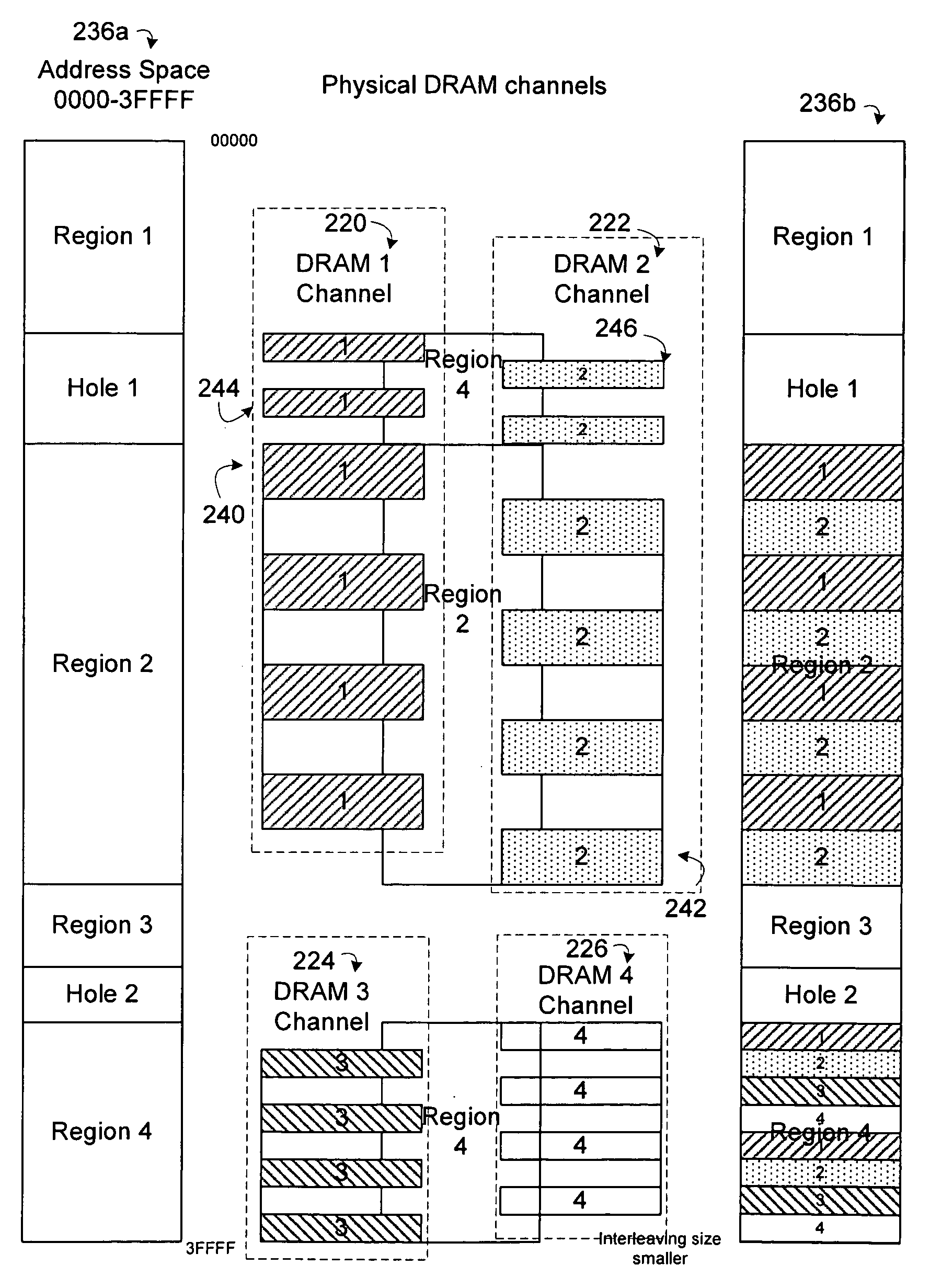
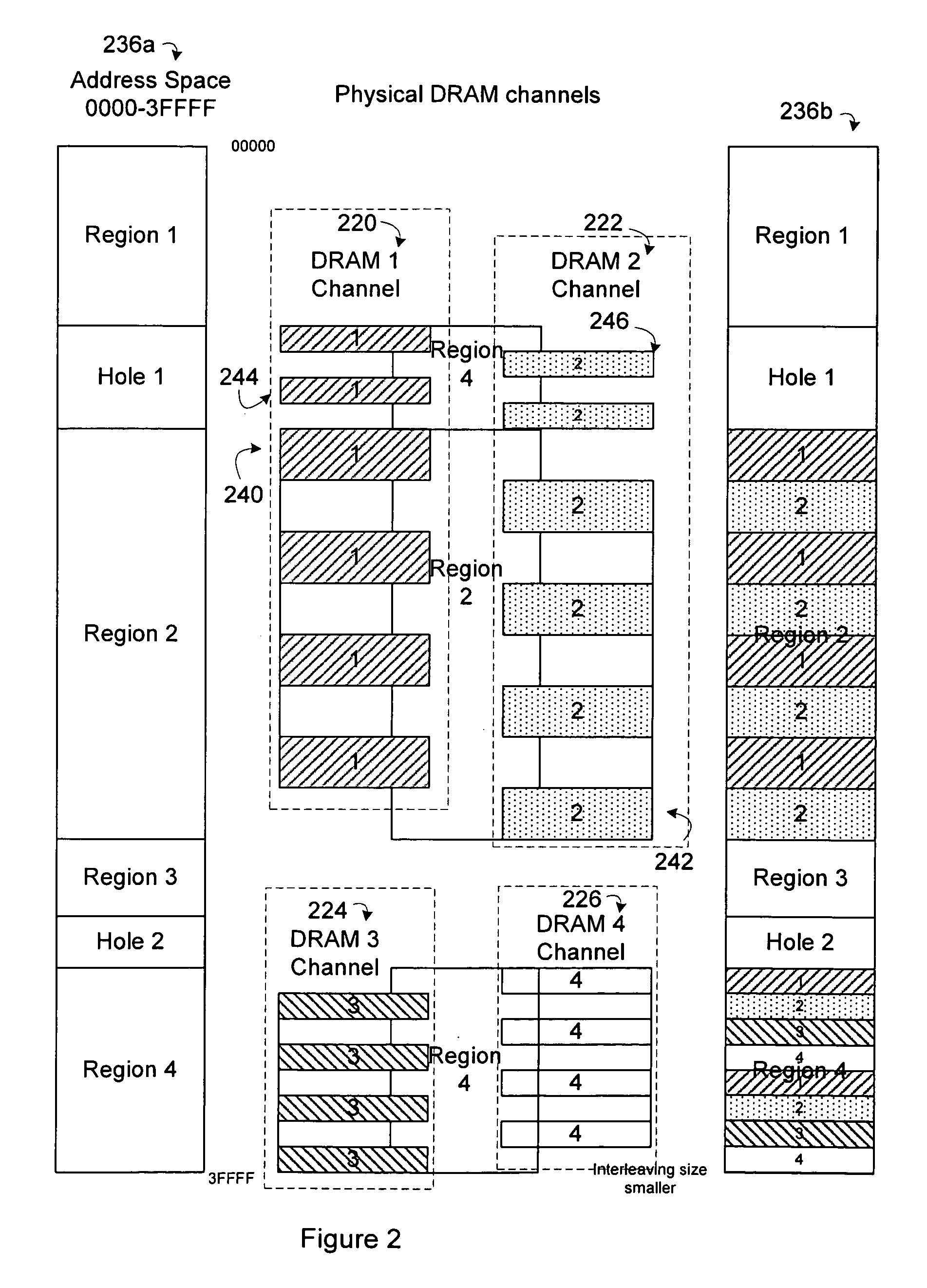
In an embodiment, an interconnect for an integrated circuit communicates transactions between one or more initiator Intellectual Property (IP) cores and multiple target IP cores coupled to the interconnect. Two or more memory channels make up a first aggregate target of the target IP cores. The two or more memory channels populate an address space assigned to the first aggregate target and appear as a single target to the initiator IP cores. The interconnect implements chopping logic to chop individual two-dimensional (2D) transactions that cross the memory channel address boundaries from a first memory channel to a second memory channel within the first aggregate target into two or more 2D transactions with a height value greater than one, as well as stride and width dimensions, which are chopped to fit within memory channel address boundaries of the first aggregate target.

Description

RELATED APPLICATIONS[0001]This application is related to and claims the benefit of U.S. Provisional Patent Application Ser. No. 60 / 946,096, titled “AN INTERCONNECT IMPLEMENTING INTERNAL CONTROLS,” filed Jun. 25, 2007.NOTICE OF COPYRIGHT[0002]A portion of the disclosure of this patent document contains material that is subject to copyright protection. The copyright owner has no objection to the facsimile reproduction by anyone of the software engine and its modules, as it appears in the Patent and Trademark Office Patent file or records, but otherwise reserves all copyright rights whatsoever.FIELD OF THE INVENTION[0003]Embodiments of the invention generally relate to an interconnect implementing internal controls.BACKGROUND OF THE INVENTION[0004]When an SOC has multiple DRAM interfaces for accessing multiple DRAMs in parallel at differing addresses, each DRAM interface can be commonly referred to as a memory “channel”. In the traditional approach, the channels are not interleaved, so...

Claims


Application Information

Patent Timeline
IPC IPC(8): G06F12/10G06F12/00
CPCG06F12/0607Y02D10/13G11C7/1072G06F15/17375Y02D10/00
Inventor WINGARD, DREW E.CHOU, CHIEN-CHUNSWARBRICK, IAN ANDREWHAMILTON, STEPHEN W.VAKILOTOJAR, VIDA
Owner META PLATFORMS TECH LLC
Learn More