
Hybrid manual-electronic pipette

a technology of manual operation and electronic pipette, which is applied in the direction of liquid/fluent solid measurement, laboratory glassware, instruments, etc., can solve the problems of lack of feedback in terms of manual systems, and achieve the effect of improving or customizing the performance of the pip

Active Publication Date: 2009-01-01
RAININ INSTR
View PDF18 Cites 7 Cited by
  • Summary
  • Abstract
  • Description
  • Claims
  • Application Information

AI Technical Summary

Benefits of technology

[0014]One embodiment of a hybrid manual-electronic pipette according to the present invention comprises a plunger mounted for manual movement in a housing to and from a stop to aspirate a fluid into and dispense the fluid from a tip extending from the housing. The pipette is further provided with a real-time electronic sensor, a low-power microcontroller, and a simple yet flexible user interface.
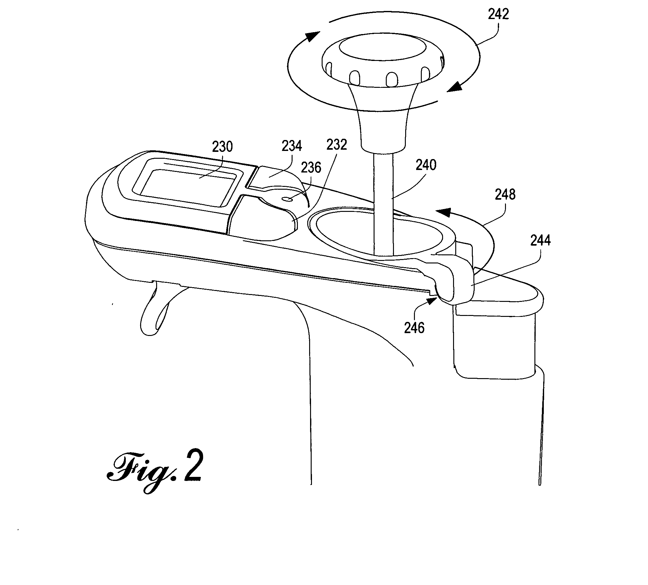
[0026]In a pipette according to an embodiment of the invention, an axially moveable volume setting member in the housing defines the stop and a volume setting for the pipette and is axially moveable by a user turnable volume adjusting member. The plunger is coupled to an air displacement piston and a highly accurate and reliable electronic position sensor component, which in turn allows measurements to be provided to a low-power microcontroller and display, thereby enabling real-time feedback on the position of the plunger, calibration of volume settings based not only on the position of the volume adjusting stop but also on the actual position of the plunger and the air displacement piston, and numerous enhanced pipetting functionality modes and capabilities not practicable with traditional fully mechanical pipettes or current state-of-the-art manual pipettes with electronic displays. The direct and tight (i.e. substantially free of slack) coupling of the plunger to the air displacement piston and sensor component eliminates mechanical backlash, while the microcontroller and user interface facilitate increased utility and ease of use. Multiple calibration functions permit the highly accurate and precise operation, by compensating not only for position sensor signal variations from pipette to pipette, but also for the non-linear but relatively invariant physical characteristics of small volumes of liquids and how they interact with the liquid end of a pipette.

Problems solved by technology

Manual systems however lack any form of feedback in terms of exactly where the plunger is positioned and hence the actual volume being aspirated or dispensed.

Method used


Image

  • Hybrid manual-electronic pipette
  • Hybrid manual-electronic pipette
  • Hybrid manual-electronic pipette

Examples


Embodiment Construction

[0076]The invention is described below, with reference to detailed illustrative embodiments. It will be apparent that a system according to the invention may be embodied in a wide variety of forms. Consequently, the specific structural and functional details disclosed herein are representative and do not limit the scope of the invention.

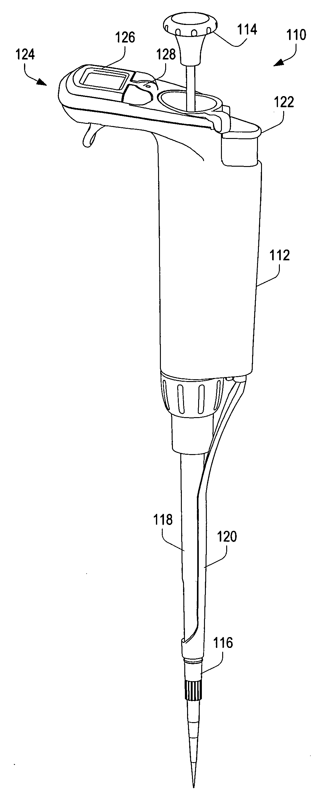
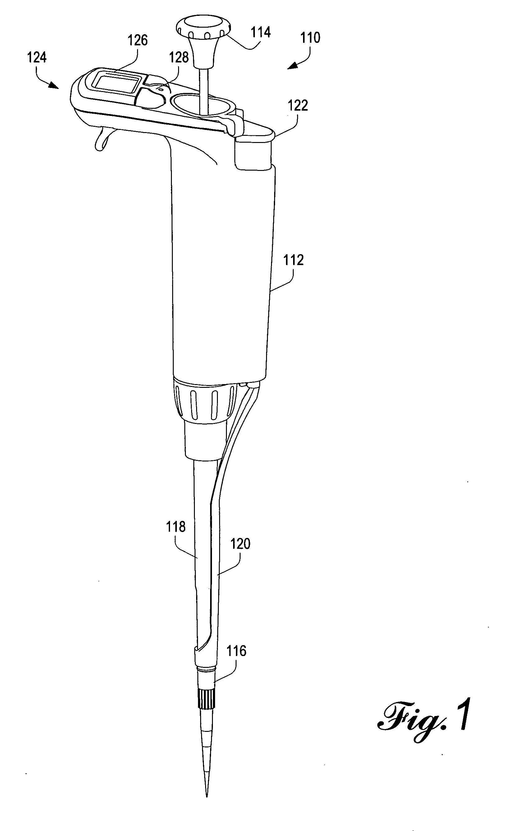
[0077]Referring initially to FIG. 1, an overview illustration of a hybrid manual-electronic pipette 110 according to the invention is presented. In general configuration, the hybrid manual-electronic pipette 110 is similar to a traditional pipette, in that a user grips a handheld body 112 of the pipette 110 and manipulates a spring-loaded plunger button 114 to control the intake and discharge of fluids through a disposable tip 116, which is coupled to a liquid end 118 of the pipette 110.

[0078]As in traditional “air displacement” pipettes, the plunger button 114 operates a piston configured to displace air within the liquid end 118; movement of air ca...


PUM


Abstract

A hybrid manual-electronic pipette combines a manually driven piston with real-time electronic measurement of liquid volume and piston displacement while compensating for both pipette-specific and pipette model-specific variations. The hybrid nature of the pipette facilitates increased accuracy and improved ease of use, and enables additional functionalities not practicable with traditional manual pipettes.

Description

CROSS-REFERENCE TO RELATED APPLICATION[0001]This application claims the benefit under 35 U.S.C. Section 119(e) of U.S. Provisional Application No. 60 / 947,367, filed on Jun. 29, 2007 and entitled “HYBRID MANUALLY-OPERATED PIPETTE WITH ELECTRONIC VOLUME MEASUREMENT,” which is owned by the assignee of the present invention and is hereby incorporated by reference in its entirety.BACKGROUND OF THE INVENTION[0002]The present invention relates to volume adjustable manual pipettes and, more particularly, to a manually-operated pipette equipped with an electronic piston position sensor and user interface.[0003]U.S. Pat. No. 3,827,305 (“the '305 patent”) describes one of the earliest commercially available digitally adjustable air displacement pipettes. To provide for volume adjustment, the pipette includes a threaded shaft extending through a fixed nut. Manual turning of the shaft produces axial movement of a stop member for limiting axial movement of a plunger to define a volume setting for...

Claims


Application Information

Patent Timeline
Patent Type & Authority Applications(United States)
IPC IPC(8): G01F25/00B01L3/02
CPCB01L3/0217B01L3/0237B01L2200/08B01L2200/143Y10T436/2575B01L2300/024B01L2300/027B01L2300/0627Y10T436/25625B01L2300/023
Inventor MAGNUSSEN, HAAKON T.PETREK, JAMES S.HOMBERG, WILLAM D.
Owner RAININ INSTR
Learn More