Pedal apparatus for vehicle

a technology for pedals and vehicles, applied in the direction of mechanical control devices, process and machine control, instruments, etc., can solve the problems of fatigue of drivers, pedal effort, and inability to let drivers so as to reduce pedal effort, reduce fatigue of drivers, and easily know the maximum operational position of pedals

Inactive Publication Date: 2009-01-01
DONG HEE IND
View PDF10 Cites 30 Cited by
  • Summary
  • Abstract
  • Description
  • Claims
  • Application Information

AI Technical Summary

Benefits of technology

[0010]An object of the invention is to provide a pedal apparatus for a vehicle that is designed to reduce pedal effort applied when the driver steps on the pedal to pivot the pedal arm, in order to reduce the driver's fatigue, and allow the driver to easily know the maximum operational position of the pedal arm.

Problems solved by technology

The pedals are frequently operated by the driver when the vehicle is traveling and the frequent operation makes the driver tired especially in a long-distance travel.
However, most apparatuses for reducing pedal effort that have been used in the related art simply reduce the pedal effort for operating the pedal that is applied by the driver and cannot let the driver know the maximum operational position of the pedal.
Pedal apparatuses equipped with a device that is separated from the apparatus for reducing pedal effort and lets the driver know the maximum operational position of the pedal have been developed to overcome the above problem; however, the pedal apparatuses still has a problem in that the cost and the weight are increased.

Method used


Image

  • Pedal apparatus for vehicle
  • Pedal apparatus for vehicle
  • Pedal apparatus for vehicle

Examples


Embodiment Construction

[0017]Hereinafter, preferred embodiments of the invention are described in detail with reference to the accompanying drawings.

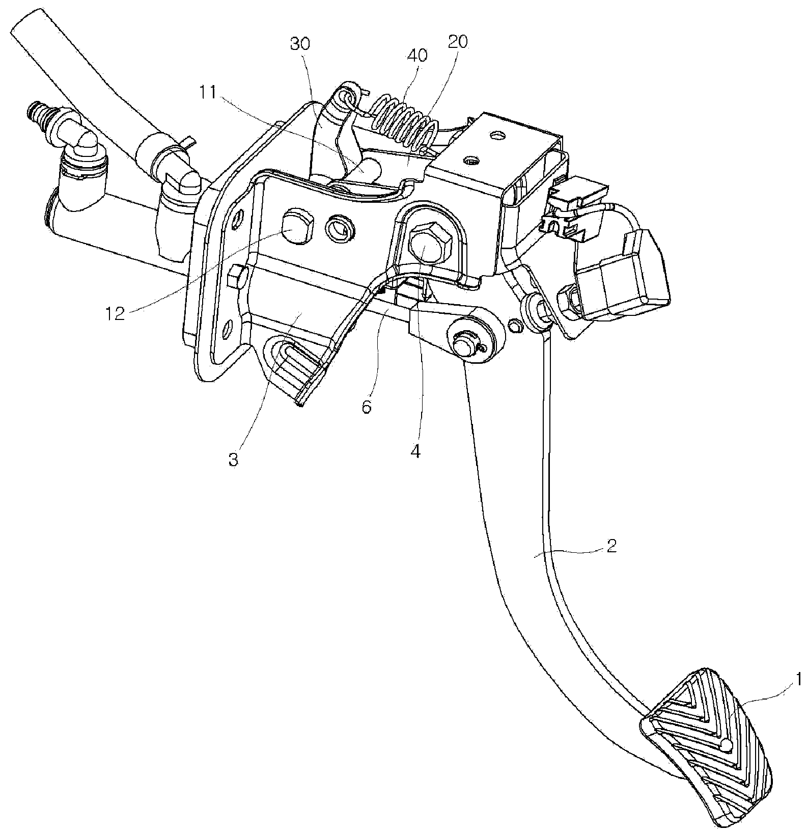
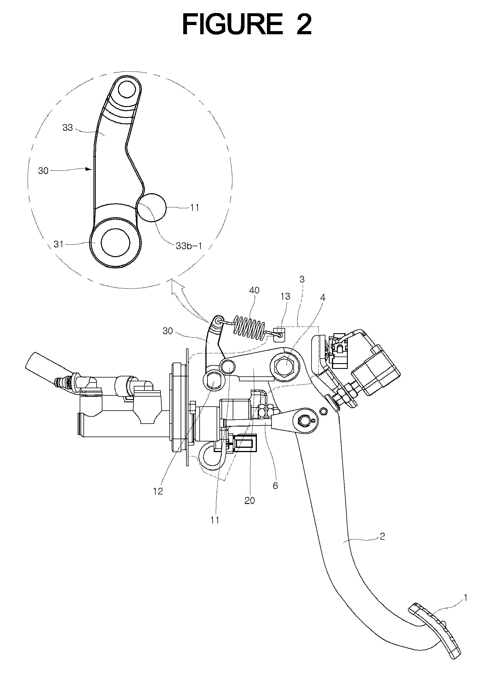
[0018]FIGS. 1 and 2 are a perspective view and a side view of a pedal apparatus, respectively, according to an embodiment of the invention.

[0019]According to a pedal apparatus of the invention, as shown in FIGS. 1 to 5, a pedal arm 2 with a pedal 1 is connected to a pedal arm mounting bracket 3 and pivots on a hinge shaft 4.

[0020]That is, the hinge shaft 4 of the pedal arm 2 passes through a hinge shaft bushing 5, such that the hinge shaft bushing 5 can rotate about the hinge shaft 4.

[0021]Further, the upper end of the pedal arm 2 is fitted around the hinge shaft bushing 5, such that as the pedal arm 2 pivots when a drive steps on the pedal 1, the hinge shaft busing 5 rotates with the pedal arm 2.

[0022]The pedal arm 2 is connected with a push rod 6, which is connected with the brake booster of a brake apparatus or a master cylinder of a clutch assembly.

[0023]...


PUM


Abstract

The present invention relates to a pedal apparatus for a vehicle, which makes it possible to reduce the driver's fatigue by reducing the pedal effort when operating the pedal arm and also allows the driver to be able to easily recognize the maximum operational position of the pedal arm.

Description

CROSS-REFERENCE TO RELATED APPLICATION[0001]The benefit of priority of Republic of Korea patent application number 10-2007-0062675, which was filed Jun. 26, 2007, is claimed pursuant to 35 USC §119(b). In addition, the contents of Republic of Korea patent application number 10-2007-0062675 are hereby incorporated by reference in its entirety.BACKGROUND[0002]1. Field of the Invention[0003]The present invention relates to a pedal apparatus for a vehicle that can be operated by a small pedal effort and allows a driver to easily know the maximum operational position of a pedal arm.[0004]2. Description of the Related Art[0005]In general, a vehicle equipped with an automatic transmission is provided with an accelerator pedal and a brake pedal, while a vehicle equipped with a manual transmission is provided with a clutch pedal for actuating a clutch, in addition to an accelerator pedal and a brake pedal.[0006]The pedals are frequently operated by the driver when the vehicle is traveling an...

Claims


Application Information

Patent Timeline
Patent Type & Authority Applications(United States)
IPC IPC(8): G05G1/30
CPCB60K23/02B60T7/065Y10T74/20528Y10T74/2107Y10T74/2101Y10T74/20534Y10T74/20888B60K26/02
Inventor KIM, KYUNGMINOH, HOJONGHEO, WONYOUNG
Owner DONG HEE IND
Why Eureka
Try Eureka