Three piece welded plastic pallet

a three-piece, plastic pallet technology, applied in the field of pallets, can solve the problems of insufficient strength of plastic pallets with a lower package height, heavy weight of pallets, and large amount of plastic materials, and achieve the effects of convenient cleaning, convenient connection, and sufficient strength

Inactive Publication Date: 2009-01-01
BUCKHORN
View PDF6 Cites 42 Cited by
  • Summary
  • Abstract
  • Description
  • Claims
  • Application Information

AI Technical Summary

Benefits of technology

[0008]A further object of the invention is to provide plastic pallet which possesses sufficient strength to support heavy loads but which is still relatively lightweight and durable.
[0009]It is another object of the invention to provide a plastic pallet which has a smooth outside surface which is easy to clean and is particularly useful in connection with handling foods and beverages.
[0010]A still further object of the invention is to provide a plastic pallet made from a synthetic resin such as polyethylene or polypropylene which is impervious to most chemicals, does not rot, does not absorb moisture, does not rust and maintains a constant tare weight.
[0011]The present invention achieves the above and other objects by providing a three piece plastic pallet constructed of a synthetic resin material and having a top deck with an upper surface and a lower surface. A middle deck is provided having an upper plate portion and lower portion spaced from each other and connected by plurality of columns extending between a lower surface of the upper plate portion and a top surface of the lower plate portion, with the upper plate portion having a top surface attached by welding to the lower surface of the top deck. A bottom deck is provided having an upper surface and a lower surface with the upper surface of the bottom deck being attached by welding to a bottom surface of the lower plate portion of the middle deck. Reinforcement members may be provided between the top deck and the middle deck and / or between the middle deck and the bottom deck to provide further strength to the pallet. Entryways for prongs of a lifting device such as a forklift may be formed on all four sides of the pallet.

Problems solved by technology

Such pallets are heavier and use relatively large amounts of plastic material.
Other plastic pallets with a lower package height may not provide sufficient strength for heavier loads.

Method used


Image

  • Three piece welded plastic pallet
  • Three piece welded plastic pallet
  • Three piece welded plastic pallet

Examples


Embodiment Construction

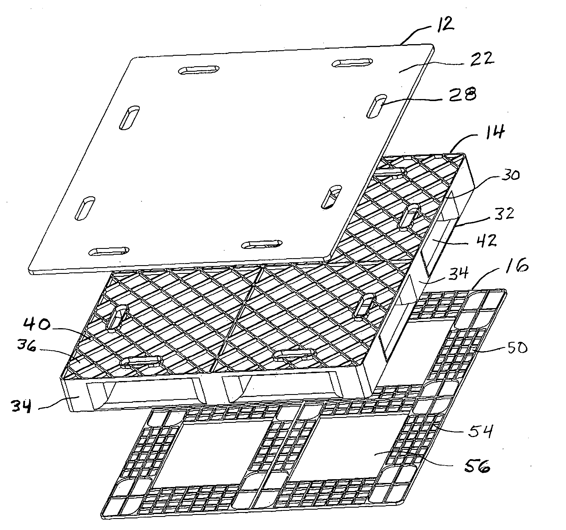
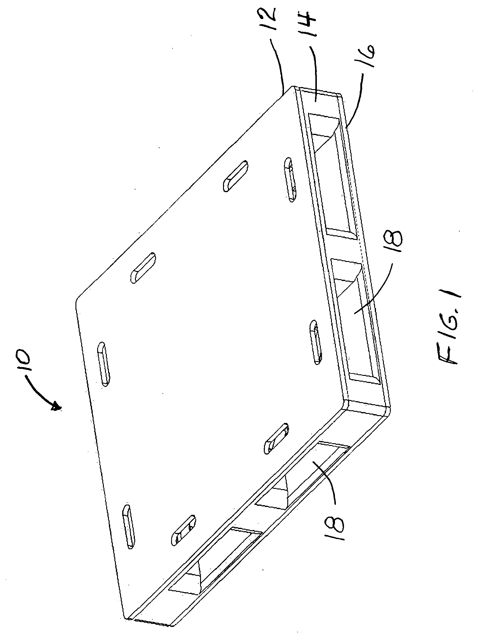
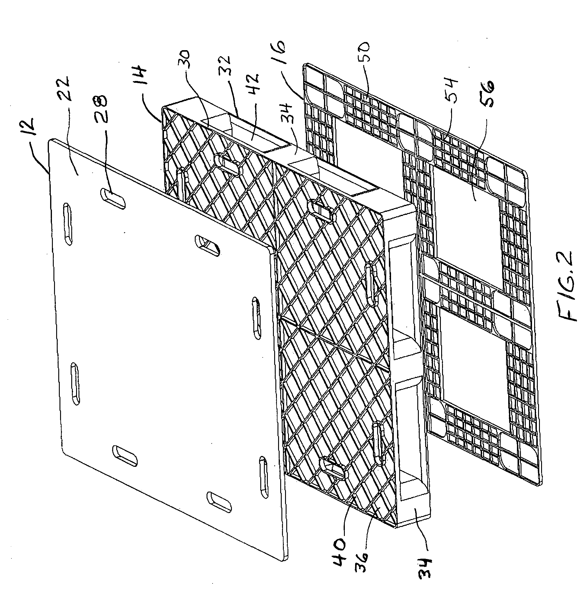
[0019]Illustrated in FIGS. 1-4 of the drawings is a pallet 10 according to the present invention which includes a top deck 12, a middle deck 14 and a bottom deck 16. A plurality of entryways 18 are provided on the sides of the pallet with each side being constructed with two entryways to receive the prongs of a lifting device such as a forklift. The top, middle and bottom decks are all made of a synthetic resin or plastic material such as polypropylene or polyethylene. The three decks preferably are molded using an injection molding process.

[0020]The top deck 12 has a smooth upper surface 22 as shown in FIGS. 1-3 and a lower surface 24 having a plurality of ribs 26 which cross each other to form a plurality of diamond shaped boxes as shown in FIG. 4. The top deck also is provided with a plurality of holes constituting hand holds 28 adjacent the sides thereof.

[0021]As shown in FIGS. 2, 3 and 4, middle deck 14 is constructed having an upper plate portion 30 and a lower plate portion 3...


PUM


Abstract

A plastic pallet constructed of a synthetic resin material includes a top deck having an upper surface and a lower surface and a middle deck having an upper plate portion and a lower plate portion connected by a plurality of columns extending there between and integrally molded as a single piece. A bottom deck has an upper surface and a lower surface. The lower surface of the top deck is welded to the top surface of the upper plate portion and the bottom surface of the lower plate portion of the middle deck is welded to the upper surface of the bottom deck. Reinforcement members may be provided between the top deck and the middle deck and between the middle deck and the bottom deck.

Description

BACK GROUND OF THE INVENTION[0001]1. Field of the Invention[0002]The present invention relates to a pallet made of synthetic resin and, more particularly, to a three piece welded plastic pallet for supporting loads that is adapted for use with a lifting device.[0003]2. Description of the Related Art[0004]Plastic pallets are becoming more commonly used in today's industries. Plastic pallets have many advantages over those made of wood or even metal. Plastic pallets are stronger and more durable than wooden pallets and are impervious to most chemicals, do not rot and do not absorb moisture. Plastic pallets are also lighter than wood or metal pallets. Moreover, plastic pallets are not subject to corrosion or rusting.[0005]Many of the plastic pallets in use today are constructed of top and bottom horizontal decks connected together by a series of columns or posts and have entryways for the forks of a lifting device such as a fork lift. In order to be strong enough to support heavier loa...

Claims


Application Information

Patent Timeline
Patent Type & Authority Applications(United States)
IPC IPC(8): B65D19/32
CPCB65D19/0016B65D2519/00791B65D2519/00069B65D2519/00104B65D2519/00129B65D2519/00273B65D2519/00288B65D2519/00318B65D2519/00333B65D2519/00373B65D2519/00407B65D2519/00412B65D2519/00417B65D2519/00437B65D2519/00442B65D2519/00562B65D2519/00034
Inventor FICKER, PAUL
Owner BUCKHORN
Why Eureka
Try Eureka