Solar power harvester with reflective border

a solar power collector and reflective border technology, applied in the field of solar power collectors, can solve the problems of increasing the cost of fabricating, installing and maintaining such systems, prohibitively expensive systems for conventional commercial use, and typically expensive mounting or base structures for tracking structures

Inactive Publication Date: 2009-01-01
EDWARDS OLIVER J +1
View PDF25 Cites 8 Cited by
  • Summary
  • Abstract
  • Description
  • Claims
  • Application Information

AI Technical Summary

Benefits of technology

[0017](a) to provide an improved solar power harvester which can produce up to 100% gain in solar irradiance; that is: up to two suns on a given collector area.
[0020](d) to provide a solar power harvester which can return a cash value equal to its total ownership cost within a small fraction of its lifetime.

Problems solved by technology

However, the number of photovoltaic cells required on a fixed flat panel for a usable power station, considering the various positions of the sun throughout the year, is so large that the system has been prohibitively expensive for conventional commercial use.
Typically expensive mounting or base structures were required with tracking structures.
This further increased the cost of fabricating, installing and maintaining such systems.
Exposure to the environment resulted in corrosion, the most frequent cause of system failure.
In all cases the commercial practicality of these successive innovations has been critically limited by the adverse disparity between the value of the solar-generated electrical power versus the amortized aggregated cost of the concentrator structure, the drive apparatus, and the photovoltaic cells themselves.
(c) A dual-axis tracking solar collector, including the ±23.26° change in elevation as the sun moves through its seasons, can collect one-sun irradiation all day, but at the high investment and maintenance cost of mast-mounted and motorized plates of cells or small concentrators the size of a double garage door.

Method used


Image

  • Solar power harvester with reflective border
  • Solar power harvester with reflective border
  • Solar power harvester with reflective border

Examples


Embodiment Construction

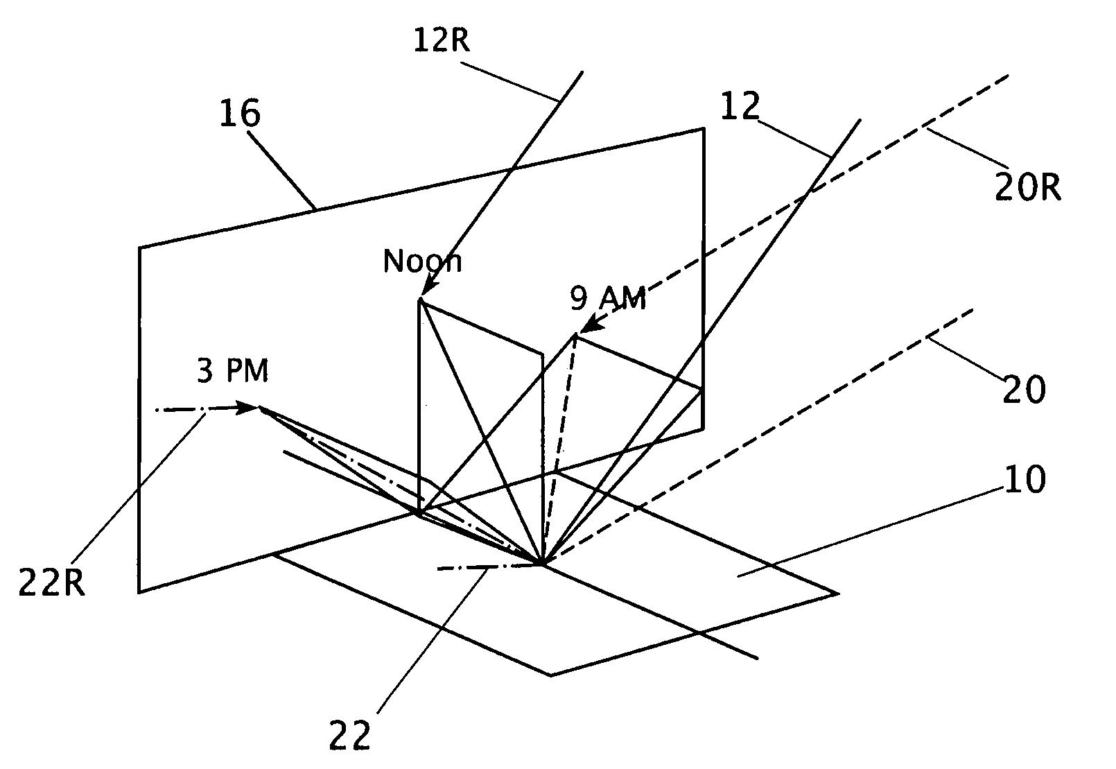
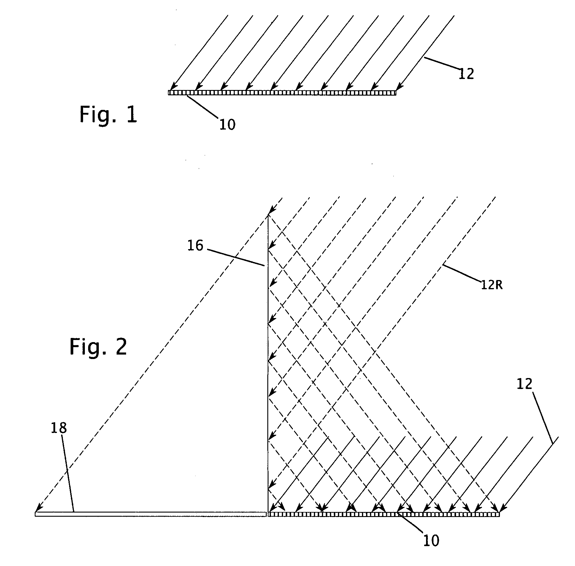
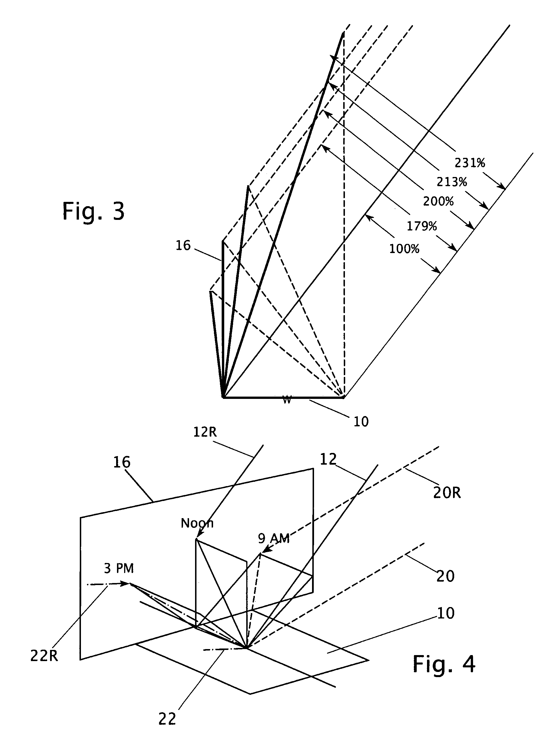
[0033]Referring first to FIG. 1, reference numeral 10 refers to a planar solar harvester. This might be of any form which harvest sunlight and converts it to useful power. This useful power might take the forms of heat and / or photovoltaic (PV) electricity. Typical examples of a planar solar harvester include (a) non-tracking: for example a sheet of contiguous PV cells or cell modules; or (b) tracking in one dimension to follow the sun: for example an array of parallel north-south oriented parabolic troughs which track the sun in an east-west direction. The plane of the harvester 10 may horizontal, or it might be sloped for some desirable purpose, such as positioning on a sloped roof.

[0034]Sunlight irradiates the harvester 10, as indicted by the sun rays 12. At noon and at the equinox of the year these are sloped from the vertical at an angle equal to the local latitude, and herein are illustrated at the latitude of San Francisco: 38° N.

[0035]At the equator, the rays 12 would be vert...


PUM


Abstract

A solar energy harvester comprises: a planar solar harvester panel serving to absorb sunlight and convert it to useful power such as electricity and / or heat; a planar north (in the northern hemisphere) wall which is specularly reflective on its south side, running east-west and positioned adjacent the north end of the harvester panel. The reflective north wall may be considered to create a second, equal, virtual harvester panel to convert additional energy, or alternately to create a virtual sun to illuminate the harvester panel from the north. The solar energy harvester effectively doubles the output of useful power of a prior art solar harvester panel alone.

Description

FIELD OF INVENTION[0001]The present invention relates to solar power collectors; and more particularly, it relates to enhancement of solar irradiation on a prior art planar solar collector.BACKGROUND OF THE INVENTION[0002]Systems for harvesting solar irradiance, of the type with which the present invention is concerned, have application in remote areas where electricity or other utilities are not readily available. However, persons skilled in the art will readily appreciate that the present invention is more broadly directed to a solar energy conversion system, whether the useful energy is in the form of electricity or heat, and irrespective of its ultimate use. Even though the invention has such broader application, it will be disclosed in the context of a source of electrical power which is useful in dwellings and office buildings.[0003]In the past, the most widely employed solar energy converters for solar power harvesting have employed a number of photovoltaic cells mounted to a...

Claims


Application Information

Patent Timeline
Patent Type & Authority Applications(United States)
IPC IPC(8): H01L31/042
CPCF24J2/16F24J2/18F24J2002/1095H01L31/0547Y02E10/40Y02E10/52Y02B10/12F24S2023/878F24S23/79F24S23/77Y02B10/10
Inventor EDWARDS, OLIVER J.HORSTMEYER, ROBERT J.
Owner EDWARDS OLIVER J
Why Eureka
Try Eureka