Distributed inverter and intelligent gateway

Inactive Publication Date: 2009-01-01
ENPHASE ENERGY
View PDF20 Cites 123 Cited by
  • Summary
  • Abstract
  • Description
  • Claims
  • Application Information

AI Technical Summary

Benefits of technology

[0020]An advantage of the invention is to provide a system and method of installation, operation, and maintenance of the a power conversion system that is simple and safe.
[0021]Another advantage of the invention is to provide a high degree of reliability and a long lifetime to the microinverter.
[0022]Yet another advantage of the invention is to provide upgradeability of the system during the lifetime of the system.
[0023]Additional features and advantages of the invention will be set forth in the description which follows, and in part will be apparent from the description, or may be learned by practice of the invention. The features of the invention will be realized and attained by the structure particularly pointed out in the written description and claims hereof as well as the appended drawings.
[0024]To achieve these and other advantages and in accordance with the purpose of the invention, an embodiment of the invention is directed towards a system for transforming energy. The system for transforming energy includes a plurality of photovoltaic modules. The plurality of microinverters are electrically coupled to the photovoltaic modules in a one-to-one relationship. The system also includes a gateway electrically coupled to the plurality of microinverters and features of the gateway are capable of being upgraded with at least one of hardware, software, and firmware.
[0025]In another aspect of the invention, an embodiment of the invention includes a gateway for use in a system for use in an energy generating system. The gateway includes an interface unit for interfacing with a plurality of microinverters

Problems solved by technology

Residential rooftops present a special challenge for the placement and interconnection of photovoltaic modules, due to the presence of gables, multiple roof angles, and other such obstructions.
Such rooftops often do not expose a sufficiently large, commonly directed surface to the sun for photovoltaic modules to be positioned to harvest maximum power.
This degrades the AC power harvest from the entire array.
Commercial buildings and larger installations present slightly different challenges.
In commercial buildings, large, commonly directed surfaces are generally available, but even then, obstructions, such as HVAC components must be dealt with as the components may block solar radiation.
Additionally, since such installations often consist of thousands

Method used


Image

  • Distributed inverter and intelligent gateway
  • Distributed inverter and intelligent gateway
  • Distributed inverter and intelligent gateway

Examples


Example

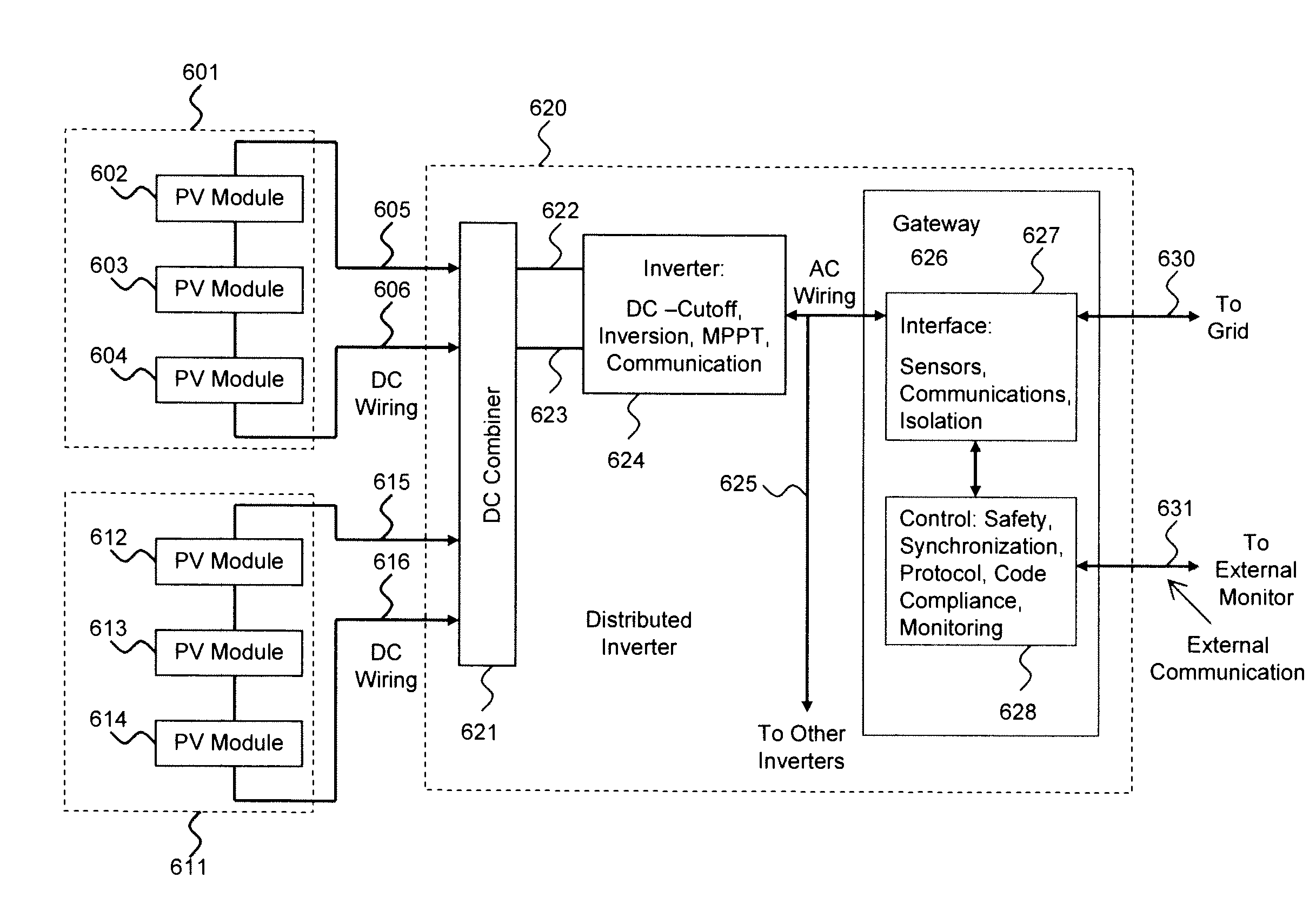
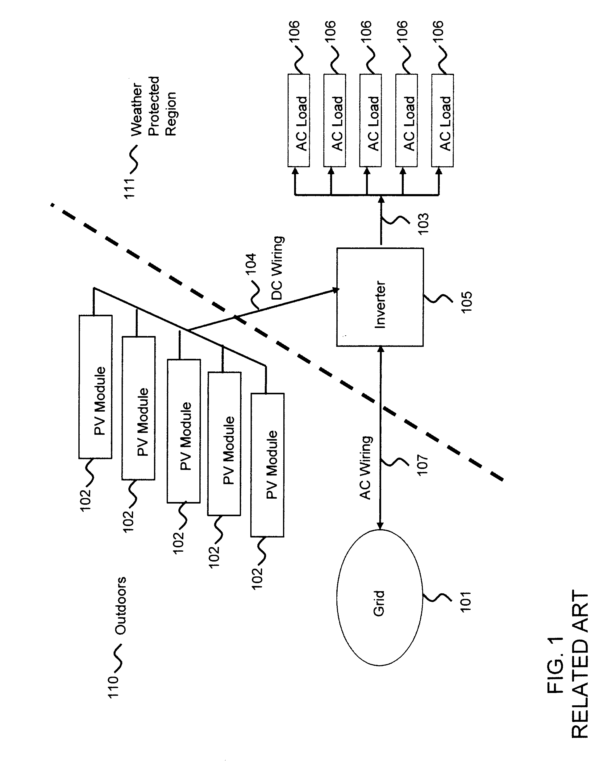
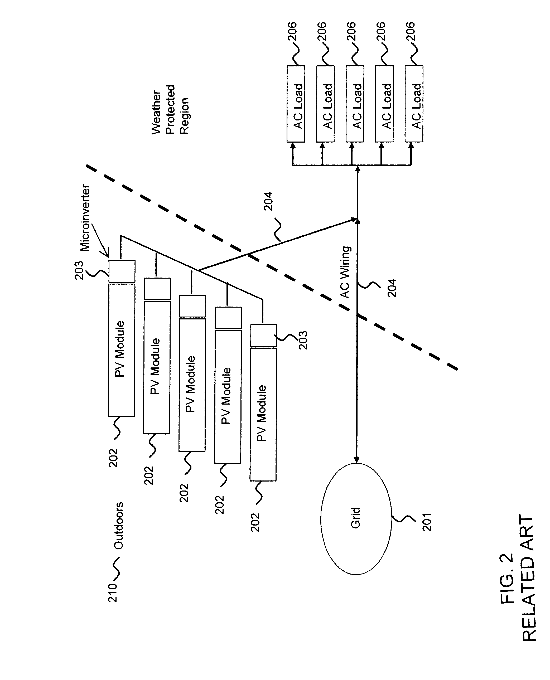
[0038]Embodiments of the invention include a novel approach whereby only those functions and components that are necessary to achieve the advantages of microinverters are placed in assemblies in proximity to the PV modules and other functions including, for example, system control, are located elsewhere. This separation of functions and components is termed portioning. The control and coordination of the system is performed without additional wiring. Communications may occur via powerline, wired and / or wireless channels. Disabling the communications channel provides a way for turning the microinverters off thereby facilitating inverter or PV module replacement, maintenance or other desired tasks. Moreover, the partitioning provides for enhanced safety as compared to the related art. In the related art, in the presence of solar radiation, the PV module outputs are always enabled and are thus capable of electrocuting the installer. Accordingly, embodiments of the invention provide for...


PUM


Abstract

A system and method for converting DC from one or more sources to AC power utilizing a novel partitioning scheme are disclosed. This partitioning scheme is particularly well suited for photovoltaic (PV) microinverter applications. The primary goals are to make installation, operation and maintenance of the system safe and simple. Secondary goals are to improve reliability and lifetime of the converter in a cost effective manner. In one embodiment, the microinverters are placed in one-to-one proximity with the photovoltaic modules, each proximate microinverter incorporating a reduced number of functions and components. Remaining common functions and controls are implemented separately.

Description

[0001]The present application relates to and claims the benefit of priority to U.S. Provisional Patent Application No. 60 / 938,663 filed May 17, 2007, which is hereby incorporated by reference in its entirety for all purposes as if fully set forth herein. The present application is further related to co-pending U.S. patent application Ser. No. LAR004 entitled, “Photovoltaic AC Inverter Mount and Interconnect” and U.S. patent application Ser. No. LAR003 entitled “Photovoltaic Module-Mounted AC Inverter”, both of which are hereby incorporated by this reference in their entirety.BACKGROUND OF THE INVENTION[0002]1. Field of the Invention[0003]The invention relates to power conversion including direct current (DC) to alternating current (AC) and, more particularly, to photovoltaic module output power conversion to AC.[0004]2. Discussion of the Related Art[0005]In coming years, distributed generation of electricity is likely to become a larger and larger part of the energy sourced to utili...

Claims


Application Information

Patent Timeline
IPC IPC(8): H01L31/042
CPCH02M7/493Y02B10/14Y02E10/563H02J3/387Y02E10/763H02J3/385H02J3/386Y02E10/58H02J3/383H02J2300/30H02J2300/28H02J2300/26H02J2300/24H02J3/381Y02E10/76H02J3/40H02J3/38Y02B10/10Y02E10/56H02J3/388H02M7/44
Inventor ROTZOLL, ROBERT R.KAPUR, RAJAN N.PATIL, SUHAS S.
Owner ENPHASE ENERGY
Why Eureka
Try Eureka