Oil pressure control device having a damper for suppressing pressure dither

a technology of oil pressure control device and damper, which is applied in the direction of valve operating means/releasing devices, mechanical equipment, transportation and packaging, etc., can solve the problems of large and difficult mounting of bulky and heavy oil pressure control valves on automobiles, so as to avoid the increase in size and weight of the control device

Inactive Publication Date: 2009-01-01
DENSO CORP
View PDF6 Cites 14 Cited by
  • Summary
  • Abstract
  • Description
  • Claims
  • Application Information

AI Technical Summary

Benefits of technology

[0010]The present invention has been made in view of the above-mentioned problem, and an object of the present invention is to provide an improved oil pressure control device, in which a single damper oil passage common to plural spool valves is provided, avoiding increase in size and weight of the control device.
[0013]Since the oil-retaining space is common to all of the oil-damper chambers, the valve case can be made compact. Since the oil-retaining space is positioned above the oil-damper chambers, air entered into the oil-damper chambers is easily pushed up into the oil-retaining space. Therefore, the oil-damper chambers and the orifices are filled with oil thereby to enhance damping effects. Since the oil-retaining space formed in the horizontal direction in the valve body is positioned close to the oil-damper chamber, a breathing hole including the orifice connecting the oil-retaining space and the oil-damper chamber can be easily made by drilling in the vertical direction.

Problems solved by technology

This makes the width of the valve body 2 wide, and makes the oil pressure control valve bulky and heavy.
It is not easy to mount a bulky and heavy oil pressure control valve on an automobile.

Method used


Image

  • Oil pressure control device having a damper for suppressing pressure dither
  • Oil pressure control device having a damper for suppressing pressure dither
  • Oil pressure control device having a damper for suppressing pressure dither

Examples


Embodiment Construction

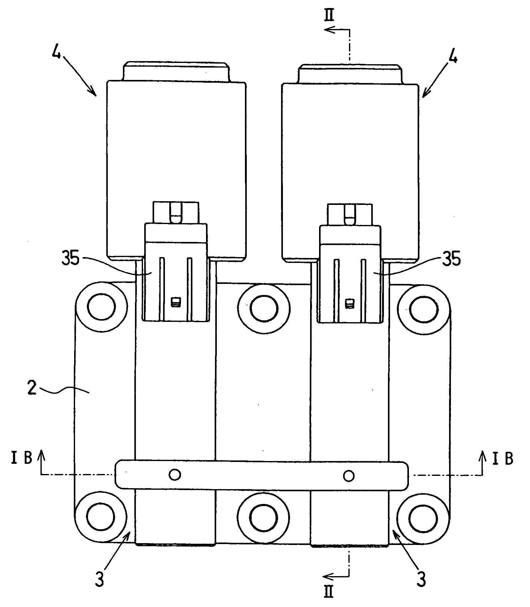
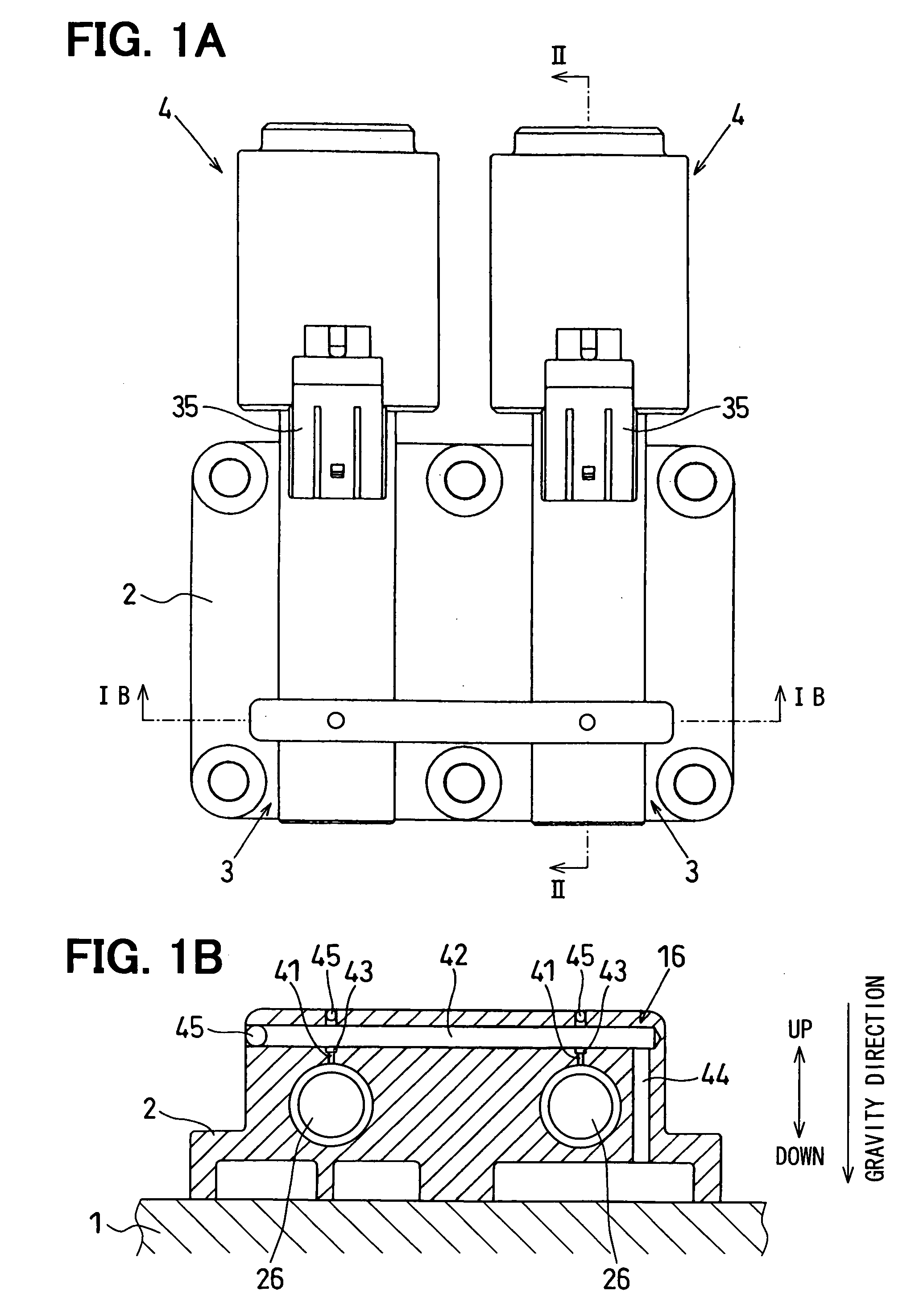
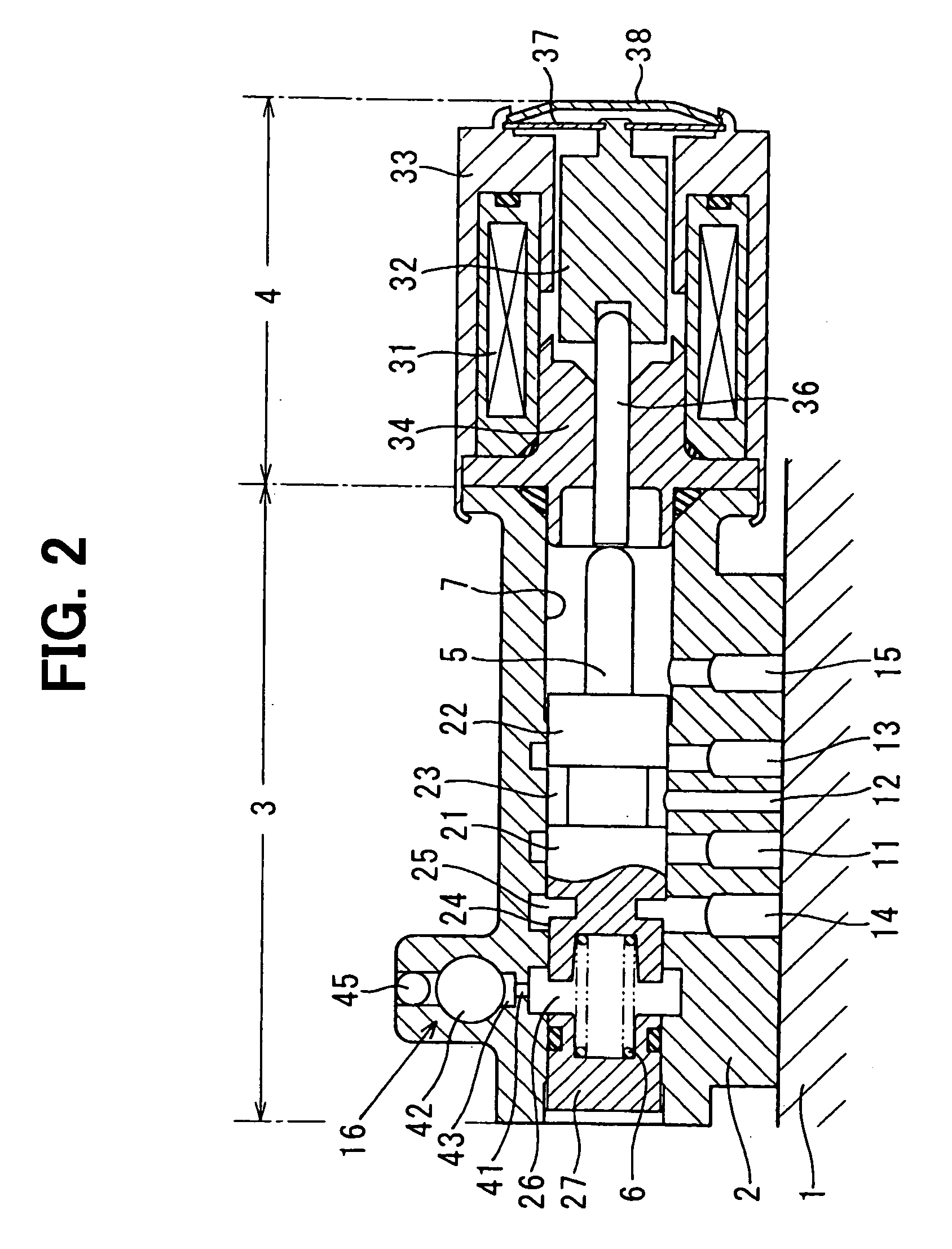
[0024]In the preferred embodiments described below, the present invention is applied to an oil pressure control device for supplying oil to an automatic transmission device mounted on an automotive vehicle. The oil pressure control device includes plural spool valves each having an oil-damper chamber and a damper oil passage common to all of the oil-damper chambers. A bottom surface of the oil pressure control device is connected to an upper surface of a case containing the automatic transmission device (referred to as an AT case).

[0025]A first embodiment of the present invention will be described with reference to FIGS. 1A, 1B and 2. The automatic transmission device mounted on an automotive vehicle includes various friction-operated components which are controlled by oil supplied from the oil pressure control device. The oil pressure control device controls pressure of the oil to be supplied to the automatic transmission device according to control signals fed from an electronic c...


PUM


Abstract

An oil pressure control device of the present invention is used for controlling oil pressure supplied to an automatic transmission device for an automotive vehicle. The oil pressure control device includes two or more spool valves driven by electromagnetic actuators. A spool forming the spool valve is slidably disposed in a cylindrical hole formed in a valve body. An oil-damper chamber is connected to an axial end of the cylindrical hole to suppress micro-vibrations of the spool caused by driving frequencies of the electromagnetic actuator. An oil-retaining space common to all the oil-damper chambers is formed in the valve case above the oil-damper chambers. Each oil-damper chamber is connected to the common oil-retaining space through an orifice. The oil-damper chamber and the orifice are filled with damper oil, and thereby the micro-vibrations of the spool are effectively suppressed.

Description

CROSS-REFERENCE TO RELATED APPLICATION[0001]This application is based upon and claims benefit of priority of Japanese Patent Application No. 2007-172115 filed on Jun. 29, 2007, the content of which is incorporated herein by reference.BACKGROUND OF THE INVENTION[0002]1. Field of the Invention[0003]The present invention relates to an oil pressure control device including an oil-damper chamber for suppressing dither in controlled oil pressure. The oil pressure control device is used, for example, in an automatic transmission device mounted on an automotive vehicle.[0004]2. Description of Related Art[0005]A spool valve has been often used in an oil pressure control valve for an automatic transmission device mounted on an automotive vehicle. The spool valve is slidably disposed in a cylindrical hole formed in a valve body and is driven by an electromagnetic actuator or oil actuators. The oil pressure control valve controls oil pressure supplied to the automatic transmission device.[0006]...

Claims


Application Information

Patent Timeline
Patent Type & Authority Applications(United States)
IPC IPC(8): F16K31/00
CPCF16H61/0251F16K31/0696F16K31/0613F16H2061/004Y10T137/86485
Inventor INAGUMA, YOSHITSUGUISHIBASHI, RYO
Owner DENSO CORP
Why Eureka
Try Eureka