Rotatable Stapling Head Of A Surgical Stapler
a stapling head and stapler technology, applied in the direction of surgical staples, paper/cardboard containers, manufacturing tools, etc., can solve the problems of inability to solve the problem of incomplete cutting of excess tissue around the wound, requiring too much strength, and affecting patient health, so as to achieve less strength
- Summary
- Abstract
- Description
- Claims
- Application Information
AI Technical Summary
Benefits of technology
Problems solved by technology
Method used
Image
Examples
embodiment 1
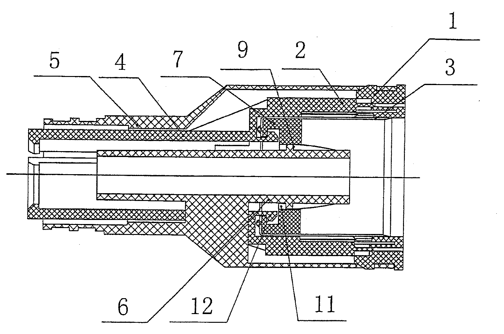
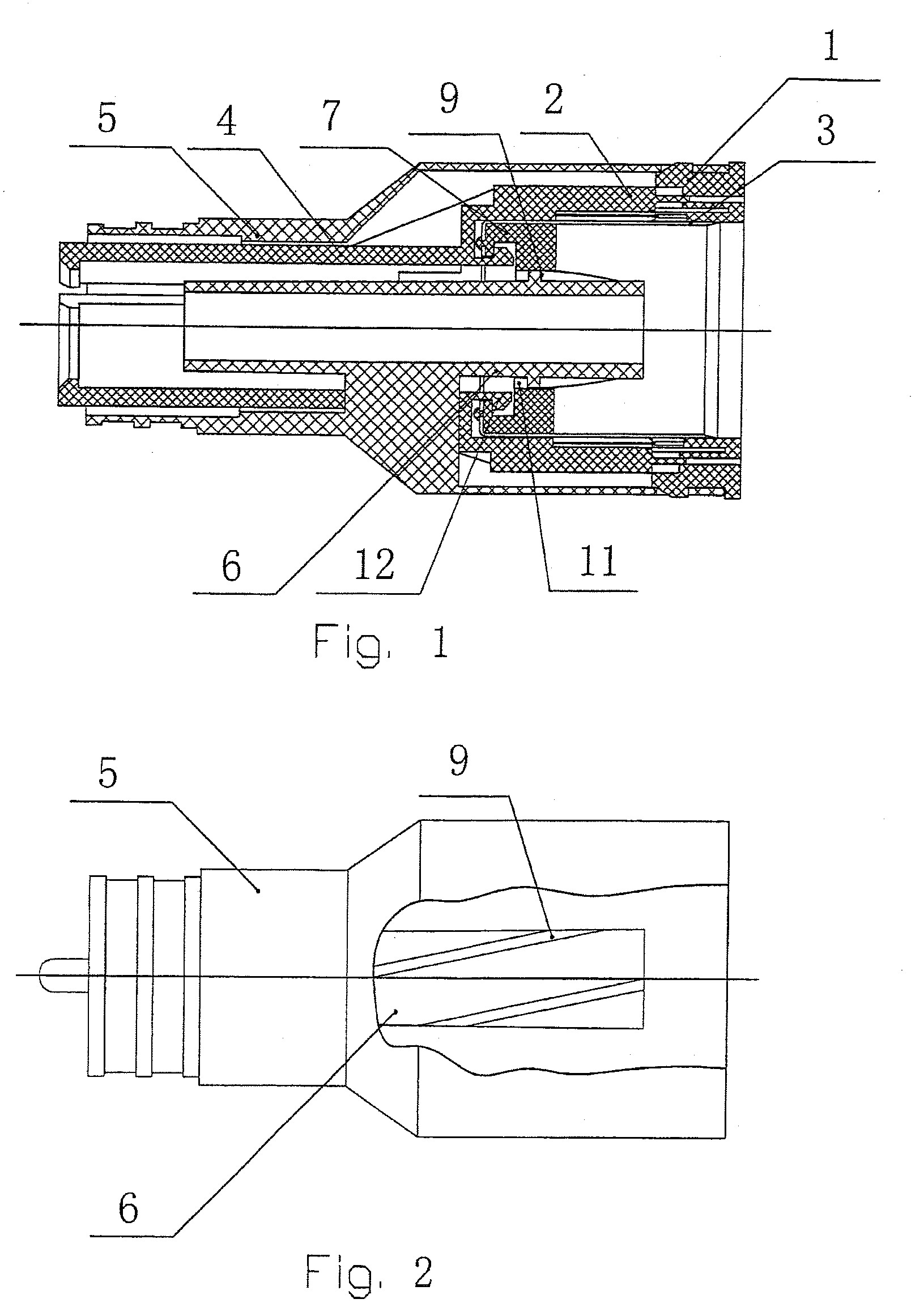
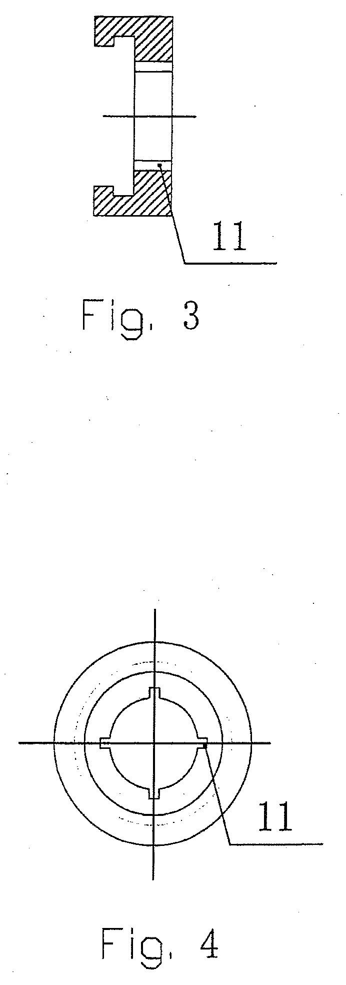
[0041]As shown in FIGS. 1 and 2, the staple driver 2 and the compression rod 4 are made integral, the rotating sleeve 7 is disposed at the inner bottom of the annular scalpel 3; the hook 12 is disposed at the bottom of the front cavity of the staple driver 2 so as to hook with the bottom of the annular scalpel 3. When the staple driver 2 is pushed forward, it drives the rotating sleeve 7 and the scalpel 3 to move forward, meanwhile, the concave-convex structure 11 of the rotating sleeve 7 matches with the spiral track 9 of the support tube 6 in the staple casing so as to drive the rotating sleeve 7 to rotate. Because the rotating sleeve 7 is riveted with the scalpel 3, the scalpel 3 rotates along with the rotating sleeve 7. After stapling, the scalpel 3 and the rotating sleeve 7 retract back to the staple casing by the force from the hook 12 which is disposed on the staple driver.
embodiment 2
[0042]As shown in FIG. 5, the staple driver 2 and the compression rod 4 are made integral, the rotating sleeve 7 is disposed at the outer bottom of the annular scalpel 3; the hook 12 is disposed at the bottom of the front cavity of the staple driver 2 so as to hook with the bottom of the rotating sleeve 7. When the staple driver 2 is pushed forward, it drives the rotating sleeve 7 and the scalpel 3 to move forward, meanwhile, the concave-convex structure 11 of the rotating sleeve matches with the spiral track 9 of the support tube 6 in the staple casing so as to drive the rotating sleeve 7 to rotate. Because the rotating sleeve 7 is riveted with the scalpel 3, the scalpel 3 rotates along with the rotating sleeve 7. After stapling, the scalpel 3 and the rotating sleeve 7 retract back to the staple casing by the force from the hook 12 which is disposed on the staple driver.
embodiment 3
[0043]As shown in FIG. 6, the staple driver 2 and the compression rod 4 are made integral, the rotating sleeve 7 is disposed at the inner bottom of the annular scalpel; a fixed spiral sleeve 13 is fixed outside the support tube 6, the spiral track 9 is disposed on the outer wall of the fixed spiral sleeve, the support tube 6 has a threaded insert 8 on its front end with a limit fastening nut 10 disposed thereon. A hook 12 is disposed at the bottom of the front cavity of the staple driver 2 so as to hook with the bottom of the rotating sleeve 7. When the staple driver 2 is pushed forward, it drives the rotating sleeve 7 and the scalpel 3 to move forward, meanwhile, the concave-convex structure 11 of the rotating sleeve matches with the spiral track 9 of the fixed spiral sleeve so as to drive the rotating sleeve 7 to rotate. Because the rotating sleeve 7 is riveted with the scalpel 3, the scalpel rotates along with the rotating sleeve 7. After stapling, the scalpel 3 and the rotating ...
PUM
| Property | Measurement | Unit |
|---|---|---|
| shape | aaaaa | aaaaa |
| concave-convex structure | aaaaa | aaaaa |
| strength | aaaaa | aaaaa |
Abstract
Description
Claims
Application Information
 - R&D
- Intellectual Property
- Life Sciences
- Materials
- Tech Scout
- Unparalleled Data Quality
- Higher Quality Content
- 60% Fewer Hallucinations
Browse by: Latest US Patents, China's latest patents, Technical Efficacy Thesaurus, Application Domain, Technology Topic, Popular Technical Reports.
© 2025 PatSnap. All rights reserved.Legal|Privacy policy|Modern Slavery Act Transparency Statement|Sitemap|About US| Contact US: help@patsnap.com


